1. Introduction
1.1 The WEC-Pro vision and industry context
The WEC-Pro project (Progressing Wave Energy Conversion via Large-Scale Additive Manufacturing) aims to fundamentally disrupt the traditional, slow-moving development cycle of WECs by harnessing the transformative capabilities of LFAM. Historically, marine manufacturing has evolved through distinct waves: from wood, to steel, to GRP.1 Today, the industry is poised at the beginning of its logical “fourth wave” driven by LFAM.2
MRE innovation has been severely bottlenecked by the prohibitive capital costs, inflexible tooling, and extended lead times associated with conventional fabrication. By replacing rigid workflows with agile, tool-less LFAM technologies, it becomes possible to rapidly iterate, physically test, and seamlessly optimise complex, hydrodynamically efficient geometries at a fraction of the historical cost. Ultimately, this paradigm shift democratises access to large-scale prototyping, accelerating the trajectory of novel wave energy concepts from laboratory conceptualisation to commercial-scale offshore deployment.
1.2 R&I agenda objectives
This agenda serves as a collaborative roadmap for affiliated institutions and potential stakeholders. The core objectives are to:
•
Identify Key Industry Challenges: Map current LFAM capabilities against stringent marine structural requirements, extreme wave loads, and harsh corrosive environments.
•
Formulate Targeted Strategies: Develop actionable engineering solutions to enhance material durability, maximise hydrodynamic efficiency, and guarantee geometric stability.
•
Establish Workflows: Create a comprehensive 7-step methodology from digital design to final class certification, aligning with existing maritime guidelines (e.g., DNV, ABS, LR).
•
Define Economic Metrics: Establish the financial indexes and predictive formulas—specifically Capital Expenditure (CapEx), Operational Expenditure (OpEx), and Levelized Cost of Energy (LCOE)—required to prove LFAM’s competitiveness against traditional shipbuilding.
2. Structural and regulatory constraints
2.1 Extreme environmental loading
Marine structures installed in the ocean must be designed and manufactured to withstand significant environmental loads over operational lifespans that often span decades. Unlike terrestrial infrastructure, offshore systems are continuously subjected to a highly dynamic, multi-directional loading environment. These environmental forcings are dominated by extreme wave actions, storm surges, and strong ocean currents, which collectively dictate the ultimate limit state (ULS) and fatigue limit state (FLS) of the structures. Ensuring survivability under these extreme conditions is paramount, as structural failure not only leads to catastrophic financial losses but also poses severe environmental and safety hazards.
Industry Challenges: Wave loads on offshore structures are amplified by highly nonlinear phenomena, including:
•
Sloshing & Slamming: Violent, impulsive impacts of water against structural surfaces, characterised by extremely short-duration, high-intensity pressure peaks (up to 250 kPa for small vessels). In shallow waters or during severe storms, these intense transient forces severely threaten the structural integrity of the hull.
•
Wave Breaking & Overtopping: Shock pressures from plunging breakers that can be orders of magnitude higher than non-breaking wave loads. Overtopping events lead to “green water” loading on decks and superstructures, imposing severe transient vertical loads.
•
Coupled Mooring Dynamics: Deepwater floating platforms and WECs rely on elastic mooring systems rated for extreme environmental loading. Nonlinear restoring forces and low-frequency drift motions can lead to extreme tension peaks (snap loads) at attachment points, necessitating precisely-tuned mooring stiffness and damping characteristics.
Strategy & Required Action: To effectively mitigate these extreme environmental loads while maintaining economic and structural efficiency, the stakeholders will implement the following targeted strategies and required actions:
•
Digital Twins and Load Mapping: Integrate advanced Computational Fluid Dynamics (CFD) and structural Finite Element Analysis (FEA) to accurately map extreme hydrodynamic loads onto digital twins of the WEC floaters.2
•
Topology Optimisation: Utilise advanced topology optimisation algorithms to distribute material strictly along primary load paths. This approach replaces the traditional shipbuilding method of uniformly increasing plate thickness, thereby drastically reducing overall weight and material costs without compromising survivability.
•
Filling Geometry and Lattice Structures: Exploit LFAM’s design freedom to print complex internal filling geometries. By incorporating shockabsorbing lattices (such as auxetic, honeycomb, or gyroid unit cells), the printed structures can achieve localised deformation and superior energy dissipation during violent slamming events.
•
Custom Structurally Efficient Material Selection: Select and compound high-performance, marine-grade materials tailored for extreme impact and fatigue loads. This includes utilising fibre-reinforced thermoplastic composites and functionally graded materials that offer exceptional specific strength, stiffness, and impact resistance.
•
Localised Thickening and Part Consolidation: Leverage the tool-less nature of LFAM to seamlessly integrate localised thickening in high-stress hull sections. Furthermore, consolidate multiple components into monolithic prints to eliminate vulnerable welded or bolted joints, which typically serve as failure initiation sites under extreme cyclic loading.
Figure 1 illustrates the wave pressure on a horizontal plate for different types of extreme waves estimated by suitable wave theories, within the Le Méhauté’s wave diagram.2
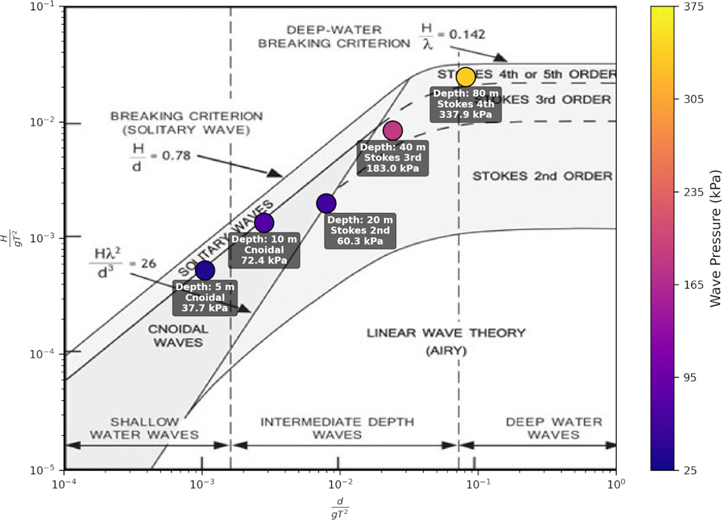
Figure 1. Wave pressure on a horizontal plate for different types of extreme waves estimated by suitable wave theories, within the Le Méhauté wave diagram (Adapted from2).
2.2 Standards and certification landscape
The maritime and offshore energy sectors are inherently risk-averse, prioritising long-term reliability, survivability, and safety above all else. Consequently, certifying innovative manufacturing methods remains a significant bottleneck for the commercialisation of novel technologies. Marine structures must comply with stringent standards set by major classification societies, which historically rely on decades of empirical data derived from traditional subtractive or formative manufacturing processes. The introduction of LFAM disrupts these established paradigms, presenting unique regulatory challenges related to material anisotropy, process repeatability, and defect characterisation. Without clear, standardised certification pathways, MRE developers face insurmountable barriers to securing project financing, insurance, and regulatory approval for offshore deployment.2
Industry Challenges: The certification of LFAM for marine applications is hindered by several critical hurdles, such as (not limited to):
•
Lack of Historical Data: The absence of long-term empirical performance data for massive, monolithic 3D-printed structures makes it difficult to validate and approve primary load-bearing components for offshore use.
•
Absence of Consolidated Rules: While general AM guidelines exist, there is a distinct lack of mature, marine-specific certification rules tailored to the unique scale, environmental exposure, and material behaviours of LFAM.
•
Process Repeatability and Anisotropy: The layer-by-layer nature of LFAM introduces inherent material anisotropy and potential microstructural defects, complicating standard testing, inspection, and qualification procedures.
Strategy & Required Action: To overcome these regulatory hurdles and pave the way for commercial adoption, the following targeted strategies and actions are required:
•
Alignment with Emerging Frameworks: Strictly align the manufacturing workflow with newly released AM-specific frameworks from major classification societies.
Table 1 summarises the critical international standards and guidelines that must be navigated to achieve certification.2
•
Documentation of Design and LSAM Specifications: Establish and rigorously document design allowables, material properties, and specific LFAM machine parameters. This ensures that every printed component is traceable to a frozen, qualified Manufacturing Procedure Specification (MPS).
•
Digital Thread and Metadata Integration: Generate a robust “digital thread” by linking comprehensive metadata directly to the LSAM-produced parts. This includes aggregating raw material certificates, in-situ thermal and optical monitoring logs, and post-build Non-Destructive Testing (NDT) reports to facilitate part-family qualification and continuous quality assurance.
•
Client Co-Engineering: Work side-by-side with clients, naval architects, and MRE developers throughout the entire product lifecycle. This collaborative approach ensures that the final printed components strictly adhere to project-specific operational requirements and regulatory constraints from the earliest design phases.
•
Development of Guidelines and Best Practices: Propose and publish standardised guidelines, end-to-end workflows, and industry best practices for marine LFAM. This proactive knowledge sharing will help demystify the certification process and establish a baseline for future stakeholders.
•
Real-World Case Studies and Demonstrators: Develop, test, and document real case studies of functional marine components. By physically validating these demonstrators in relevant environments (e.g., wave tanks or openwater deployments), the necessary empirical data will be provided to allow classification societies to confidently approve LFAM structures.
Table 1. Standards and guidelines relevant to Large-Format Additive Manufacturing for Marine Applications.
|
Standard (Date) | Name | Relevance to LFAM |
|---|
| ISO/ASTM 52910:18 | Design—Requirements, guidelines | AM design rules for robust LFAM geometry and reduced waste. |
| ISO/ASTM 52901:17 | General principles—Purchased AM parts | Procurement criteria and traceability for LFAM part qualification. |
| ISO/ASTM 52920:23 | Qualification principles—Ind. AM processes | Site-level qualification: process control, personnel, equipment. |
| Material extrusion (polymers)
| | |
| ISO/ASTM 52903–1:20 | Mat. extrusion—Part 1: Feedstock | Feedstock specs for pellet-fed LFAM: moisture, size, melt flow. |
| ISO/ASTM 52903–2:20 | Mat. extrusion—Part 2: Equipment | Hardware/process requirements for LFAM setup and acceptance. |
| ASTM F3529–21 | Guide—Design—Mat. Extrusion (Poly) | Design guidance for LFAM: bead size, raster, overhangs. |
| Validation, capability, data and reporting
| |
| ISO/ASTM 52902:19 | Test artefacts—Geometric capability | Accuracy/distortion mapping for LFAM build volumes. |
| ISO/ASTM 52950:21 | Overview of data processing | AM data chain for LFAM job tickets and traceability. |
| Marine Classification Society Guidelines
|
| DNV–ST–B203 | Additive manufacturing | Qual. framework for AM metals and polymer for energy & maritime; includes CO2 appendix. |
| ABS 322 | Requirements for Additive Manufacturing | Standardised qualification of AM facilities, feedstock & parts for marine and offshore.
|
| LR Guidance Notes | AM Metallic Parts/Polymer AM Cert. | Goal-based certification to meet class requirements for ships and offshore.
|
3. LFAM technologies for marine applications
3.1 Robotic architectures and kinematics
To accommodate the massive dimensions and geometric intricacies of MRE structures, LFAM systems rely on diverse and highly adaptable kinematic setups. Unlike desktop additive manufacturing, printing marine components—such as multi-metre wave energy floaters, twisted tidal turbine blades, and complex hull forms—requires hardware capable of operating across vast build envelopes while manipulating heavy extrusion or welding end-effectors. The transition from conventional manufacturing to automated LFAM necessitates robotic architectures that not only provide the physical reach required for shipbuilding but also the agility to execute complex, multi-axis toolpaths.2
Industry Challenges: Scaling additive manufacturing to the marine level introduces several critical kinematic and operational hurdles:
•
Geometric Limitations and Scalability: Traditional Cartesian and gantry systems provide exceptional stability for heavy payloads but are typically limited to 3-axis planar deposition. This strictly restricts the fabrication of complex, overhanging marine geometries without relying on massive, wasteful support structures.
•
Consistent Part Reproducibility: Maintaining tight dimensional tolerances and consistent material deposition across build volumes spanning several metres is highly difficult. Minor kinematic inaccuracies or vibrations at the robotic end-effector can compound over large distances, leading to unacceptable geometric deviations.
•
Structural Quality and Certification: Ensuring the structural integrity of large-scale prints requires absolute kinematic precision. Any deviation in the toolpath or deposition speed can lead to fatal microstructural defects (e.g., voids, poor layer adhesion) that compromise the part and prevent class certification.
•
Supply Chain Integration and Automation: Integrating massive robotic printing cells into existing shipyard logistics, as well as automating the continuous delivery of raw materials (tons of pellets or metal wire) and the handling of the finished heavy components, remains a significant logistical bottleneck.
Strategy & Required Action: To overcome these hardware limitations and enable the scalable production of marine structures, the following strategies and actions are required:
•
Advanced 6-Axis Kinematics: It is necessary to deploy articulated 6-axis industrial robotic arms mounted on metre-scale linear rails or mobile tracked platforms. This architecture vastly expands the operational workspace and overcomes the geometric constraints of traditional 3-axis gantry systems.2
•
Non-Planar Printing Strategies: The extended degrees of freedom provided by robotic arms must be utilised to implement non-planar toolpaths. This is essential for producing highly curved, hydrodynamically optimised surfaces and aligning material deposition with primary structural load paths.
•
Cooperative Multi-Robot Systems: Future R&I efforts are required to explore and implement multi-robot architectures operating in tandem. Synchronising multiple deposition heads on a single massive part will drastically reduce production lead times and mitigate thermal gradient issues.
•
Closed-Loop Kinematic Control: Real-time spatial tracking and closedloop feedback systems must be integrated into the robotic controllers to dynamically correct toolhead positioning. This ensures consistent part reproducibility and guarantees structural quality across the entire build volume.
•
Automated Material Handling: To achieve true supply chain automation, the robotic cells must be integrated with automated, high-capacity feedstock delivery systems (e.g., continuous pellet dryers and pneumatic conveyors) and synchronised with shipyard lifting equipment for seamless post-print logistics.
Figure 2 illustrates the taxonomy of LFAM robotic systems, ranging from standard Cartesian gantries to specialised cooperative and multi-axis configurations for marine applications.2
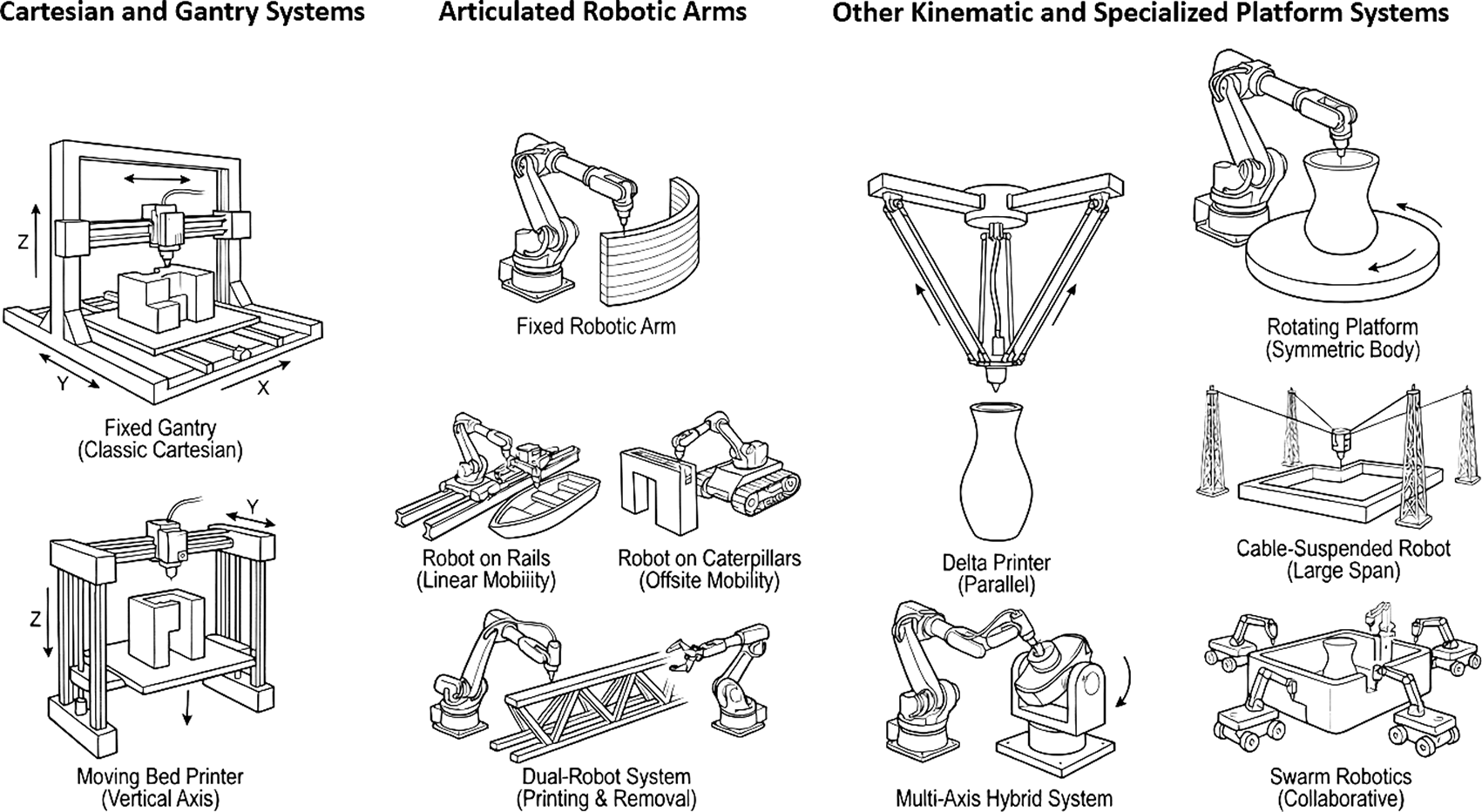
Figure 2. Taxonomy of LFAM robotic systems, ranging from standard Cartesian gantries to specialised cooperative and multi-axis configurations for marine applications (Adapted from2).
3.2 Thermoplastic LFAM (pellet extrusion)
When addressing the fabrication of massive buoyant modules, complex hull forms,
WEC floaters, and non-mission-critical superstructures, thermoplastic LFAM—specifically via Fused Granular Fabrication (FGF) or Big Area Additive Manufacturing (BAAM)—emerges as a highly optimal and disruptive solution.2 Unlike traditional desktop 3D printing that relies on costly and size-restricted filament spools, this technology utilises the direct extrusion of compounded industrial polymer pellets through a single-screw extrusion head mounted on a robotic or gantry system.
By bypassing the energy-intensive and expensive filament manufacturing stage, pellet extrusion achieves massive material deposition rates, typically ranging from 10 to 50 kilograms per hour depending on the nozzle configuration. This remarkable throughput not only accelerates production timelines from months to mere days but also drives drastic cost reductions, as raw pellets are often up to ten times cheaper than their filament counterparts. Furthermore, thermoplastic structures offer profound operational advantages tailored specifically to offshore applications. For instance, they provide total immunity to the galvanic corrosion that constantly degrades metallic marine assets, while offering outstanding, customisable buoyancy control through programmable internal lattice structures and advanced geometries.
Industry Challenges: Despite its immense potential, the widespread adoption of thermoplastic LFAM in the maritime sector must navigate several critical material and environmental limitations:
•
Material Selection Trade-offs: Selecting polymers that perfectly balance printability, cost, and resistance to the harsh marine environment is highly complex. Standard commodity plastics often fail mechanically under wave loads, while aerospace-grade polymers are economically prohibitive for massive WEC floaters.
•
Thermal Warpage and Dimensional Accuracy: Because LFAM systems deposit massive beads of molten thermoplastic (often exceeding 2–10 mm in height) without a fully enclosed, heated macro-chamber, the material experiences rapid, uneven cooling. This volumetric contraction generates enormous internal residual stresses, causing large flat panels to curl upward (warp), destroying mating tolerances and inducing premature delamination.
•
Z-Axis Anisotropy: The layer-by-layer extrusion process inherently creates weak inter-layer weld lines. Under the cyclic bending and hydrostatic pressure variations of wave loading, structural failure almost exclusively manifests as delamination along this Z-axis rather than the rupture of the polymer bead itself.
•
Environmental Degradation: Unprotected polymer surfaces are highly susceptible to hydrothermal ageing (seawater saturation) and long-term ultraviolet (UV) degradation. Constant submersion plasticises the thermoplastic matrix and chemically degrades the fibre-matrix interface, while intense solar irradiance can cause thermal softening and embrittlement.
•
Circularity and Carbon Footprint: While polymers offer lightweight advantages, relying solely on virgin petrochemical feedstocks contradicts the sustainability goals of the Marine Renewable Energy sector. Sourcing and qualifying reliable, structural-grade recycled plastics—especially from difficult-torecycle maritime waste—remains a significant supply chain hurdle.
Strategy & Required Action: To definitively overcome these barriers and ensure that 3D-printed polymer structures achieve the rigorous long-term survivability required for decades of offshore operation, the following strategies and actions are required:
•
Advanced Composite Compounding & Material Matrix Evaluation: A comprehensive matrix of materials must be evaluated and utilised, specifically targeting high-performance engineering thermoplastics.3 For example, Polypropylene (PP) offers excellent chemical resistance and low density for buoyancy; Polyethylene Terephthalate Glycol (PETG) provides superior printability and impact resistance; and advanced Polycarbonate/Polybutylene Terephthalate (PC/PBT) blends deliver exceptional structural rigidity and low moisture absorption. These base matrices must be compounded with short carbon or glass fibres (typically 15% to 30% by weight) to significantly enhance the specific strength-to-weight ratio and drastically lower the Coefficient of Thermal Expansion (CTE), thereby actively suppressing severe thermal warpage.2
•
Direct Pellet Upcycling (Circular Economy): Crucially, it is identified that championing the circular economy by integrating shredded, end-of-life maritime plastics directly into the LFAM pellet feedstock is the most highpotential solution.4 For instance, decommissioned wind turbine blades (traditionally landfilled thermoset composites) can be mechanically milled and compounded into new thermoplastic matrices, serving as recycled fibre reinforcement. A prime demonstration of this circular potential is the “Beluga” project (
Figure 3), a monolithic 3D-printed boat manufactured using MyReplast recycled composites, proving that closed-loop material lifecycles are viable for marine structures.
•
Intelligent Toolpathing and Thermal Control: To mitigate Z-axis anisotropy, slicing algorithms must be programmed with alternating layer orientations (e.g., cross-hatching) to bridge inter-layer interfaces. Additionally, localised Infrared (IR) pre-heating of the deposition zone must be utilised to minimise thermal gradients and improve layer-to-layer fusion.
•
Marine-Grade Surface Protection: To prevent hydrothermal ageing and UV degradation, it is necessary to apply advanced marine sealants. Encapsulating the printed WEC floaters in impermeable, elastomeric polyurethanes or marine-grade epoxy coatings shields the internal matrix from water absorption and biological fouling, preserving baseline fatigue strength.
•
Variable Density and Buoyancy Control: Manufacturing engineers must exploit the slicing software to program variable internal infill densities. This allows for precise, localised buoyancy and ballast control within a single monolithic print, optimising the hydrodynamic response of the WEC without requiring complex internal assembly.
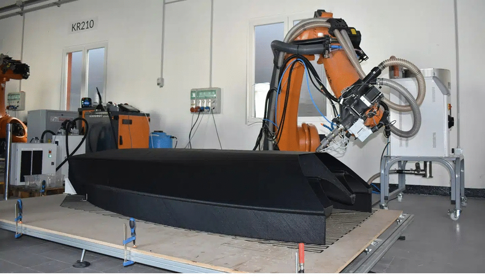
Figure 3. LFAM printed dinghy sailboat made of thermoplastic. Image courtesy of Caracol (Adapted from2).
3.3 Metal LFAM: Wire arc additive manufacturing (WAAM)
While thermoplastic extrusion is highly effective for buoyant structures and secondary fairings, the fabrication of highly loaded, safety-critical components—such as Power Take-Off (PTO) housings, heavy-duty mooring brackets, and structurally demanding tidal turbine blades—strictly necessitates the use of metal LFAM. Within the broader family of Directed Energy Deposition (DED) technologies, Wire Arc Additive Manufacturing (WAAM) has rapidly emerged as the most viable, scalable, and economically feasible process for the heavy marine sector.2 WAAM integrates advanced robotic kinematics with established electric arc welding techniques (e.g., GMAW, GTAW, or PAW), utilising standard welding wire as feedstock. By depositing metal layer-by-layer at high throughputs (often exceeding 10 kg/h), WAAM enables the near-net-shape fabrication of massive metallic structures, drastically reducing the immense material waste and long lead times traditionally associated with subtractive machining from solid forgings or custom castings.
Industry Challenges: The industrial implementation of WAAM for massive marine components must overcome several critical metallurgical and economic hurdles:
•
Thermal Volatility and Residual Stresses: The fundamental nature of the arc-based deposition process involves rapid, localised heating followed by intense cooling cycles. This severe thermal volatility inherently induces massive residual thermal stresses, frequently leading to macroscopic distortions, warping, and compromised structural integrity if not carefully managed.
•
Marine-Grade Corrosion Resistance: Offshore environments demand exceptional resistance to saltwater corrosion and hydrodynamic cavitation. Ensuring that printed alloys maintain these properties without suffering from microstructural degradation, phase imbalances, or internal porosity during the layer-by-layer welding process is highly challenging.
•
Surface Finish and Mating Tolerances: The “as-built” surface finish of WAAM components is characteristically corrugated due to thick, overlapping weld beads. Achieving the strict geometric tolerances required for precision mating interfaces or smooth hydrodynamic profiles inevitably requires extensive and costly secondary machining.
•
High Capital and Operational Costs: The prohibitive cost of proprietary, turnkey WAAM robotic cells and closed-source slicing software creates a high barrier to entry. This severely limits the widespread adoption of metal LFAM by smaller shipyards, MRE developers, and the broader maritime supply chain.
Strategy & Required Action: To overcome these thermal, metallurgical, and economic barriers, the following targeted strategies and actions are required:
•
Advanced Marine Alloy Processing: It is required to process and optimise advanced, corrosion-resistant marine alloys specifically for WAAM. This includes Nickel-Aluminium Bronze (NAB) for its outstanding resistance to cavitation, and high-strength Duplex/Super Duplex stainless steels (e.g., ER 2209).5
•
In-Situ Thermal Management: To overcome thermal distortion and control microstructural evolution, it is necessary to implement active in-situ thermal management. This includes real-time interpass temperature monitoring, active substrate cooling, and localised stress-relieving heat treatments during the deposition process.
•
Hybrid Manufacturing Routes: Implement hybrid manufacturing strategies that seamlessly integrate robotic WAAM deposition with subtractive Computer Numerical Control (CNC) milling. This “near-net-shape plus precision finishing” approach minimises material waste while guaranteeing the strict mating tolerances and smooth surfaces required for marine assemblies.
•
Cost Reduction via Open-Source and Open-Hardware: To democratise access to metal LFAM and drastically reduce CapEx, it is required to develop and deploy WAAM systems utilising off-the-shelf industrial robotic arms and standard welding power sources, driven by open-source control architectures and slicing software. This open-hardware approach mitigates vendor lock-in and significantly lowers the financial barrier for marine stakeholders.
•
Real-Time Defect Monitoring: Integrate acoustic emission sensors and melt-pool optical monitoring to detect internal porosity and lack-of-fusion defects in real-time, ensuring the structural quality required for maritime class certification.2
Figure 4 presents an example of a WAAM-fabricated vessel propeller in NickelAluminium Bronze.
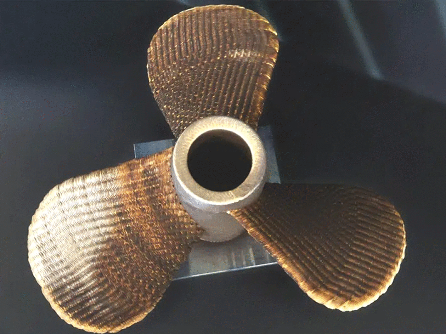
Figure 4. Example of WAAM-fabricated vessel propeller in Nickel-Aluminium Bronze. Image courtesy of Caracol (Adapted from2).
Table 2 provides an exmple of thermoplastic materials that appear to be suitable for marine LFAM applications.
Table 2. Example of thermoplastic materials evaluated for marine LFAM applications.
| Material |
ρ (g/cm3) |
σt (MPa) |
E (GPa) | Chem. Res. | UV Res. |
Wabs (%) | Recyclability |
|---|
| HDPE | 0.95 | 20 | 0.8 | High | Poor | 0.01 | High |
| PP | 0.90 | 30 | 1.5 | Good | Mod. | 0.01 | High |
| ABS | 1.04 | 40 | 2.1 | Mod. | Poor | 1.0 | Med. |
| PETG | 1.27 | 50 | 2.0 | Good | Mod. | 0.2 | High |
4. Mechanical integrity and fatigue mitigation
The long-term survivability of marine structures is fundamentally dictated by their response to cyclic loading. In the ocean environment, components are subjected to a relentless combination of high-cycle fatigue (driven by continuous wave action and turbine vibrations) and low-cycle fatigue (induced by extreme storm events and slamming loads). While the static tensile and compressive strengths of LFAM components frequently rival those of their conventionally manufactured counterparts, their fatigue behaviour is vastly more complex. The layer-wise deposition inherent to all additive manufacturing processes introduces specific microstructural and macrostructural characteristics—such as directional anisotropy, inter-layer voids, and pronounced surface roughness—that fundamentally alter crack initiation and propagation mechanics. Addressing these vulnerabilities is the most critical engineering hurdle for the widespread adoption of LFAM in safety-critical marine applications.2
4.1 WAAM fatigue challenges
WAAM is earmarked for highly loaded, mission-critical nodes such as PTO housings, heavy-duty structural joints, and mooring attachment brackets. However, the fatigue life of WAAM components in corrosive environments remains a subject of intense scrutiny.
Industry Challenges: The industrial qualification of WAAM parts is currently bottlenecked by several critical fatigue-related issues:
•
The Notch Effect and Surface Topology: The primary detriment to fatigue life in “as-built” WAAM components stems from the corrugated surface topology. The sequential deposition of molten metal beads creates pronounced layer ripples and “stair-stepping.” In fracture mechanics terms, these geometric valleys act as severe stress concentrators (micro-notches) that drastically lower the crack initiation threshold, often reducing fatigue life by up to 50% compared to machined surfaces.6
•
Internal Defects and Residual Stresses: Rapid thermal cycling during the arc process can trap shielding gas or cause localised lack-of-fusion, resulting in microscopic porosity that serves as secondary internal crack initiation sites. Furthermore, the steep thermal gradients lock massive residual tensile stresses into the part, which actively accelerate crack propagation under cyclic loads.
•
Missing Industry Data and Corrosion-Fatigue Synergies: There is a severe lack of long-term, empirical S-N (stress-life) data for WAAM alloys operating in actual seawater. The vast majority of current academic literature relies on in-air fatigue testing. This completely ignores the synergistic effects of corrosion-fatigue and hydrogen embrittlement, where the highly conductive, chloride-rich seawater electrolyte accelerates crack tip propagation. Without this data, engineers are forced to apply overly conservative safety factors, negating the lightweighting benefits of AM.
•
Standardisation of Anisotropic Assessment: Existing maritime guidelines provide excellent frameworks for process qualification, but the industry still lacks standardised, universally accepted methodologies for assessing the nonisotropic fatigue limits of massive 3D-printed metals. Traditional coupon testing often fails to capture the macro-scale residual stress fields present in fullsize marine components.
Strategy & Required Actions: To certify WAAM components for offshore deployment, the stakeholders must implement a rigorous, multi-disciplinary mitigation and testing protocol:
•
Precision Machining and Hybrid Manufacturing: CNC milling is absolutely required to completely remove the corrugated outer layer on critical load-bearing surfaces and mating interfaces. By eliminating these primary stress concentrators, the high-cycle fatigue limits of WAAM alloys (such as NAB and Duplex Stainless Steels) can be restored to near-wrought levels.2
•
Microstructural Engineering and In-Process Peening: Beyond mandatory post-weld heat treatments (PWHT) to relieve thermal stresses, research must focus on in-process mechanical treatments. Implementing interpass cold rolling or ultrasonic impact treatment (UIT) during the printing process can induce compressive residual stresses and refine the grain structure, significantly fortifying the material against cyclic crack propagation.
•
Long-Term Offshore Testing Campaigns: To close the critical data gap, the project must initiate large-scale, real-environment testing. This involves deploying WAAM test nodes in offshore splash zones to gather authentic corrosion-fatigue data. This empirical database will be shared with classification societies to develop realistic, marine-specific derating factors for additive metals.
4.2 Thermoplastic fatigue and the “Z-Axis” challenge
Thermoplastic LFAM via pellet extrusion is slated for the rapid fabrication of massive buoyant modules, WEC floaters, and hydrodynamic hull structures. While these polymer composites offer excellent specific strength and total immunity to galvanic corrosion, their fatigue behaviour in saturated environments requires careful management.
Industry Challenges: The structural integrity of 3D-printed polymers is heavily compromised by the realities of the ocean environment:
•
Z-Axis Delamination: In extruded polymers, the weakest structural link is the “Z-axis” (the inter-layer weld line). Under the cyclic bending and hydrostatic pressure variations of wave loading, structural failure almost exclusively manifests as delamination—a progressive unzipping between the printed layers—rather than the rupture of the polymer bead itself.
•
Hydrothermal Ageing and Sizing Degradation: Over a projected 20 year operational lifespan, constant submersion leads to seawater saturation within the polymer matrix. This water ingress plasticises the thermoplastic and chemically degrades the sizing at the matrix-fibre interface (in glass- or carbon-reinforced blends), causing a drastic reduction in fatigue life.7
•
Inadequate Accelerated Testing Models: Current industry methodologies rely heavily on accelerated ageing tests (e.g., boiling water immersion) to predict long-term degradation. However, these lab-scale tests frequently fail to accurately replicate the complex, synergistic effects of UV radiation, cyclic mechanical loading, and biological fouling experienced in real operational environments.
•
Lack of Non-Isotropic Design Codes: Adapting traditional composite standards to LFAM is highly problematic. LFAM parts possess distinct mesostructures and higher void contents compared to traditional vacuum-infused composites, meaning standard classical laminate theory (CLT) cannot be directly applied to predict fatigue life without significant modification.
Strategy & Required Actions: To guarantee the structural integrity of largescale polymer WEC hulls, the following advanced engineering and testing strategies are required:
•
Non-Planar Slicing and 3D Toolpathing: We must move beyond traditional 2.5D planar slicing. By utilising the full kinematic freedom of 6-axis robotic arms, toolpaths can be programmed to deposit material along the principal stress vectors of the component. This non-planar deposition strategy effectively eliminates the weak Z-axis in critical load-bearing areas, aligning the high-strength continuous extrusion paths with the incoming wave forces.
•
In-Situ Consolidation Technologies: To maximise inter-layer polymer chain entanglement, the extrusion process must be augmented with localised, in-situ heating. Utilising infrared (IR) or laser heating directly at the nip point (where the new bead meets the previous layer) will significantly increase the Z-axis weld strength and reduce internal void formation.
•
Marine Sealants and Adhesion Optimisation: Printed WEC floaters must be encapsulated in impermeable, elastomeric polyurethanes or marinegrade epoxies to shield the matrix from water absorption and UV degradation.
A critical research priority is developing specialised primer formulations that ensure these coatings adhere strongly to the corrugated, low-surface-energy profiles of LFAM polymers without flaking off under cyclic hull flexing.
Creep-Fatigue Seawater Test Rigs: The stakeholders must develop specialised test rigs that combine continuous seawater immersion with cyclic mechanical loading. By testing large-scale printed coupons under these combined conditions, the project will generate the missing long-term creep-fatigue data required to establish accurate, LFAM-specific safety factors for marine design engineers.
5. Thermal distortion and the “Warping” phenomenon in LFAM
Large-Format Additive Manufacturing inherently scales up not only the physical dimensions of the printed components but also the magnitude of the thermo-mechanical challenges associated with polymer extrusion. Unlike desktop 3D printing, where the build environment is easily controlled within a heated, enclosed chamber, LFAM of massive marine structures typically occurs in open-air or semi-controlled shipyard environments. Consequently, managing the thermal history of the deposited material becomes one of the most critical engineering tasks. Failure to control these thermal dynamics inevitably leads to severe dimensional inaccuracies and structural defects, most notably the “warping” phenomenon, which can render large-scale marine components entirely unusable and lead to massive material and financial waste.
5.1 The physics of thermal distortion
In LFAM of thermoplastic polymers and composites, the most pervasive geometrical defect is thermal distortion, commonly referred to as the “warping” phenomenon. This defect is driven by the inherent thermal gradients generated during the layer-by-layer extrusion process. As a newly deposited, semi-molten polymer bead cools from its melt temperature to ambient conditions, it undergoes volumetric shrinkage. Because this shrinking top layer is fused to a previously deposited, cooler, and already-contracted layer, a severe mismatch in thermal contraction occurs.
For semi-crystalline polymers (such as Polypropylene or High-Density Polyethylene, which are highly desirable for marine applications due to their chemical resistance), this thermal contraction is severely compounded by crystallisation kinetics.
As the polymer chains fold into dense crystalline structures during cooling, additional volumetric shrinkage occurs. The sheer scale of marine components means these microscopic contractions accumulate over metres of printed material.
This mismatch generates immense internal residual stresses—specifically, tensile stresses in the upper layers and compressive stresses in the lower layers. When these accumulated macroscopic residual stresses exceed the stiffness of the printed part or the adhesion force to the build plate, the edges of the component curl upward, detaching from the print bed and severely distorting the final geometry.11
Industry Challenges:
•
Geometric Constraints of Marine Designs: WEC floaters, hull sections, and bulkheads often require massive, flat bottom plates or wide flanges for assembly. These large planar surface areas maximise the accumulation of linear residual stresses, making them highly susceptible to catastrophic warping.
•
Loss of Watertight Tolerances: Warpage not only ruins the strict dimensional tolerances required for the watertight assembly of modular marine components but also physically deforms the intended hydrodynamic profile of the device.
•
Mid-Print Failure: The internal stresses generated by warping can exceed the Z-axis inter-layer bond strength, inducing premature delamination and catastrophic mid-print splitting before the part even experiences operational hydrodynamic loading.12
5.2 Material-level mitigation: Fibre reinforcement and blending
Unfilled semi-crystalline polymers exhibit exceptionally high CTEs, making them practically unprintable in large flat geometries without massive heated chambers—a solution that is economically and logistically unfeasible for metre-scale marine structures.
Strategy & Required Actions:
•
Composite Compounding: To restrict polymer chain mobility and drastically reduce the CTE, it is required to exclusively utilise composite feedstocks compounded with short carbon or glass fibres (typically 15% to 30% by weight). As demonstrated by Duty et al.,13 the alignment of these high-stiffness fibres along the print direction during extrusion restricts longitudinal shrinkage, reducing the CTE by up to an order of magnitude compared to the neat resin, thereby fundamentally suppressing the driving force of warpage.
Polymer Blending: The stakeholders will explore blending highly crystalline polymers with amorphous polymers (e.g., PC/PBT blends). Amorphous polymers shrink significantly less upon cooling because they do not crystallise. Blending them provides a critical balance between the excellent chemical resistance of crystalline structures and the dimensional stability of amorphous structures.
5.3 Process, toolpath, and DfAM-level mitigation
Beyond material selection, the thermal history and physical constraints of the part must be actively managed through advanced Design for Additive Manufacturing (DfAM) and intelligent robotic control.
Strategy & Required Actions:
•
Thermo-Mechanical Simulation (Digital Twin): Before physical deposition, it is necessary to utilise transient thermo-mechanical FEA to predict residual stress accumulation. By applying the inherent strain method, the CAD model can be digitally pre-deformed (morphed) in the opposite direction of the predicted warpage, ensuring the final cooled part shrinks into the correct nominal dimensions.14
•
In-situ Thermal Management: The robotic end-effector must be equipped with localised IR pre-heating lamps. By precisely reheating the substrate layer just below its glass transition temperature (Tg) immediately prior to new material deposition, the thermal gradient (∆T) is minimised, which relaxes residual stresses and simultaneously improves Z-axis weld strength.15
•
Stress-Relieving Toolpaths: Standard rectilinear infill patterns create long, uninterrupted vectors that accumulate massive shrinkage forces. It is required to implement fractal, space-filling curves (e.g., Hilbert or Gyroid patterns) and short-segment cross-hatching. These non-linear toolpaths continuously alter the deposition vector, effectively disrupting the continuous accumulation of longitudinal stress and preventing the edges of large marine plates from warping upward.16
•
Dynamic Layer Dwell Time Control: The slicing software must dynamically adjust printing speeds to control layer dwell times. If a layer is printed too quickly, heat accumulates and causes structural slumping; if printed too slowly, the layer over-cools, maximising the thermal gradient for the subsequent layer. Algorithmic control ensures a consistent thermal envelope throughout the multi-day print.
•
Mechanical Anchoring & Substrate Adhesion: Implement advanced build plate technologies, including specialised polymer-compatible adhesives and mechanical anchoring techniques (e.g., printing the first layers onto a sacrificial perforated board). This physically locks the foundational layers in place, resisting the upward curling forces during the critical initial cooling phase.
•
DfAM for Warpage Resistance: Purely flat objects must be redesigned by naval architects to feature slight curvatures, stress-relieving fillets, or integrated stiffening ribs. Eliminating sharp 90-degree corners in the CAD model prevents the concentration of shrinkage stresses that typically initiate edge lifting.
6. Hydrodynamic implications and surface finish
The transition from smooth, moulded composite hulls to 3D-printed marine structures introduces a fundamental shift in fluid-structure interaction. The inherent layer-by-layer deposition process of LFAM leaves a distinct, corrugated surface texture known as the “stair-stepping” effect. In the context of marine hydrodynamics, this macro-roughness (ks) is not merely an aesthetic defect; it acts as a severe disruptor to the boundary layer flow. When a marine structure moves through water, the surface irregularities protrude through the viscous sublayer, triggering premature turbulent transition, increasing skin friction drag, and providing an ideal, sheltered substrate for aggressive biological fouling. Managing this fluid-solid interface is critical, as excessive drag directly translates to severe energy losses, reduced power capture for renewables, and massive fuel penalties for motorised vessels.2
Industry Challenges: The hydrodynamic penalties associated with LFAM surfaces present several critical technical and economic hurdles:
•
The “Fully Rough” Regime and Drag Penalties: At the high Reynolds numbers typical of marine operations (Re > 106), the viscous sublayer becomes extremely thin. Standard LFAM layer heights (ks ≈ 2.0–5.0 mm) easily penetrate this layer, pushing the hydrodynamic profile into the “fully rough” regime. In this state, the skin friction coefficient (Cf) deviates completely from the smooth ITTC-57 baseline and levels off at a constant, highly elevated value.
Severe Fuel and Carbon Footprint Penalties: For high-speed, dragsensitive applications like planing hulls or patrol vessels, the quantitative impact of this roughness is staggering. An untreated LFAM hull with a 4 mm layer height can experience a 40% to 60% increase in frictional resistance compared to a smooth GRP hull. This translates directly to a 20% to 30% increase in fuel consumption, drastically inflating operational expenditures (OpEx) and generating a massive carbon footprint that entirely negates the environmental benefits of using recycled 3D-printed materials.
•
The Post-Processing Cost Paradox: To restore hydrodynamic efficiency, the printed surface must be smoothed. However, traditional post-processing—such as manual application of epoxy fairing compounds, extensive sanding, or 5-axis CNC milling—is incredibly labour-intensive and slow. Secondary finishing can account for 40% to 60% of the total component cost and double the manufacturing lead time, effectively destroying the primary economic advantages of tool-less additive manufacturing.
•
Biofouling Amplification: The deep valleys between printed layers create micro-environments shielded from high shear flows, providing ideal attachment points for micro-algae and barnacles. This accelerated biofouling exponentially increases the effective roughness over time, further degrading performance.
Strategies & Required Actions: To mitigate these hydrodynamic penalties while preserving the economic viability of LFAM, the following advanced manufacturing and design strategies are required:
•
Adaptive Multi-Height 3D Printing: To minimise the stair-stepping effect on highly curved hydrodynamic surfaces without sacrificing overall print speed, slicing software must be upgraded to support dynamic, adaptive layer heights. By utilising advanced extrusion control, the robot can deposit thick layers (e.g., 5–8 mm) for internal infill and straight vertical walls to maximise throughput, while automatically transitioning to very thin layers (e.g., 1–2 mm) on the outer, curved hydrodynamic skin to achieve a near-net-shape finish.
•
Flow-Aligned Deposition Kinematics: The 6-axis robotic toolpaths must be explicitly programmed to orient the printed “rails” parallel to the primary fluid streamlines. When the flow runs longitudinally along the grooves, the effective hydraulic roughness is significantly reduced (acting similarly to dragreducing riblets). Conversely, transverse alignment (acting as “speed bumps”) must be strictly avoided on high-velocity surfaces.
•
Regime-Specific Finishing Tolerances: A strict, regime-specific approach to post-processing must be adopted to avoid over-engineering. Inertia-dominated structures (e.g., heaving point absorber WECs), where radiation and diffraction forces dominate over viscous drag, can tolerate “as-printed” surfaces, saving massive post-processing costs.2 Conversely, drag-sensitive devices (e.g., tidal turbine blades, fast vessels) mandate precision smoothing.
•
Automated Hybrid Finishing Systems: For components requiring smooth finishes, manual labour must be eliminated. It is required to implement hybrid manufacturing cells where the same robotic arm used for extrusion automatically switches to a subtractive milling head or an orbital sanding end-effector. This automated, in-situ finishing ensures precise hydrodynamic profiles at a fraction of the manual labour cost.
•
Application of Marine Fairing: Instead of subtractive milling (which cuts into the structural fibres), an additive smoothing approach should be explored. Automated spray systems can be deployed to fill the layer valleys with lightweight, syntactic marine epoxy fairing compounds, followed by anti-fouling topcoats, restoring the hydrodynamic profile while sealing the polymer matrix from water ingress.
Figure 5 illustrates the hydrodynamic impact of LFAM surface roughness on skin friction coefficient across Reynolds number regimes.2
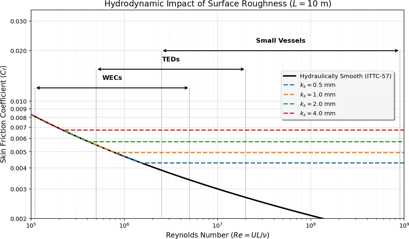
Figure 5. Hydrodynamic impact of LFAM surface roughness (ks) on skin friction coefficient (Cf) across Reynolds number regimes (Adapted from2).
7. Proposed 7-step LFAM marine workflow
The transition of Large-Format Additive Manufacturing from a laboratory prototyping novelty to a certified, industrial-scale production method requires a fundamental restructuring of the traditional shipbuilding workflow. Conventional marine manufacturing relies on a linear, highly segmented process: design, mould-making (or steel cutting), manual assembly, and final inspection. LFAM, by contrast, is an inherently digital, highly coupled process where material properties, geometric design, and manufacturing parameters are inextricably linked. A failure to synchronise these elements early in the development cycle inevitably leads to catastrophic print failures, rejected certifications, and massive financial losses. To bridge the “valley of death” between functional prototyping and commercial offshore deployment, a standardised, end-to-end methodology must be universally adopted.2
Industry Challenges: The lack of a unified LFAM workflow presents severe bottlenecks for marine stakeholders:
•
Ad-Hoc Manufacturing Approaches: Many early LFAM adopters rely on trial-and-error “print-and-fail” methodologies. At the metre-scale, this wastes thousands of dollars in raw materials and machine time per failed iteration.
•
The Digital-Physical Disconnect: Naval architects often design optimised CAD models that are physically unprintable due to overhang constraints, thermal mass imbalances, or toolhead collision risks.
•
Retroactive Certification Failures: Attempting to certify a massive 3Dprinted structure after it has been manufactured is nearly impossible. Classification societies require continuous, documented proof of process stability that must be planned before the first layer is ever deposited.
•
Inspection Accessibility: Highly complex, topology-optimised internal lattice structures cannot be easily inspected using traditional NDT methods (like ultrasound or X-ray) once the part is fully closed.
Industry Proposition & Required Actions: To establish a repeatable, certifiable, and economically viable production pipeline, the following comprehensive 7-step methodology is established as the mandatory operational blueprint for all project stakeholders, shipyards, and MRE developers:
1.
Material & Technology Selection (MCDM & LCA Integration): The workflow must begin with a rigorous, data-driven material and process selection phase. Because the marine environment imposes a unique combination of hydrostatic pressure, cyclic fatigue, UV radiation, and severe salinity, relying on generic material datasheets is insufficient. Stakeholders can employ MultiCriteria Decision Making (MCDM) algorithms—such as the Analytical Hierarchy Process (AHP) or TOPSIS—to quantitatively balance specific strength, cost per kilogram, hydrolytic resistance, and CTE. For instance, while a standard ABS pellet might offer excellent printability, an MCDM analysis for a tidal blade would heavily penalise it for poor UV and creep resistance, steering the selection toward a carbon-reinforced PC/PBT blend or, in the case of metal WAAM, a Super Duplex stainless steel.
Crucially, Life Cycle Assessment (LCA) in accordance with ISO 14040/14044 standards must be integrated directly into this initial stage. The marine renewable energy sector operates under strict sustainability mandates; therefore, the carbon footprint of virgin petrochemical feedstocks must be evaluated against recycled alternatives. By calculating the Specific Energy Consumption (SEC) of the chosen LFAM technology and the embodied carbon of the feedstock, engineers can definitively prove the environmental superiority of the additive approach over traditional GRP layups.
• Implement formal MCDM matrices to eliminate bias in material selection, weighting environmental survivability equally with printability.
• Mandate cradle-to-gate LCA calculations for all proposed feedstocks to ensure alignment with offshore renewable sustainability targets.
• Prioritise the qualification of circular feedstocks, such as repelletised maritime plastics or recycled metal wire, to drastically lower the embodied carbon of the final structure.
2.
Re-design & Optimisation (DfAM & DfC): Traditional marine blueprints, which are optimised for welded steel plates or moulded fiberglass, cannot be directly sent to a 3D printer. The structure must undergo a fundamental digital metamorphosis through Design for Additive Manufacturing (DfAM). This involves utilising advanced topology optimisation and generative design algorithms to consolidate multi-part assemblies into monolithic structures, thereby eliminating vulnerable joints and removing unnecessary mass from low-stress regions. For buoyant structures, engineers must design internal, variable-density lattice cores (e.g., gyroids or auxetic metamaterials) that provide immense crush resistance against wave slamming while maintaining strict buoyancy targets.
Furthermore, Design for Certification (DfC) and Design for Inspection (DfI) must be implemented concurrently, aligning with guidelines such as ISO/ASTM 52910. This involves integrating anti-warping geometries—such as replacing sharp 90-degree corners with generous stress-relieving fillets to prevent thermal curling. Crucially, DfI mandates that internal cavities must not be completely sealed; the CAD model must incorporate strategically placed access ports and drainage channels to allow post-print NDT probes (like borescopes) to inspect internal weld lines and to prevent the accumulation of trapped seawater during operation.
• Abandon traditional “stiffened plate” mentalities; utilise topology optimisation to distribute material strictly along primary hydrodynamic load paths.
• Integrate self-supporting overhang angles (typically <45
°) into the core design to eliminate the need for wasteful, time-consuming sacrificial support structures.
• Enforce Design for Inspection (DfI) by embedding NDT access ports and drainage channels directly into the digital model prior to slicing.
3.
Printing Configuration (Physics-Based Simulation): Before physical extrusion begins, the digital slicing strategy must be finalised, moving far beyond basic 2.5D layer generation. This phase dictates the microstructural integrity of the final part. Engineers must define layer heights, dynamic extrusion multipliers, and, most importantly, flow-aligned toolpath orientations. By orienting the deposition vectors parallel to the primary fluid streamlines, the inherent “stair-stepping” roughness acts to guide the flow rather than disrupt it, significantly minimising hydrodynamic drag.
Because LFAM involves massive thermal inputs, it is strictly required to run physics-based G-code simulations (digital twins) prior to printing. Utilising transient thermo-mechanical FEA (such as the inherent strain method), the software predicts thermal accumulation, cooling rates, and residual stress distribution. For instance, if the simulation predicts that a flat hull section will warp by 15 mm, engineers can digitally pre-deform (morph) the CAD model by 15 mm in the opposite direction. Additionally, kinematic simulations must be executed to verify that the 6-axis robotic arm will not encounter singularities or collide with the rapidly growing part during complex non-planar trajectories.
Strategic Recommendations:
• Mandate the use of transient thermo-mechanical digital twins to predict and counteract residual stress and thermal warpage before committing to physical printing.
• Utilise flow-aligned, non-planar slicing strategies to minimise transverse form drag on hydrodynamically sensitive surfaces.
• Implement dynamic layer dwell time control within the G-code to ensure a consistent thermal envelope, preventing both structural slumping and inter-layer cold cracking.
4.
Post-Processing Configuration (Hybrid Planning): In the LFAM of marine structures, post-processing is not an optional aesthetic step; it is a critical functional requirement that can account for up to 60% of the total component cost. Therefore, post-processing must be planned proactively in the digital phase, not treated as an afterthought. For components requiring precise mating tolerances (e.g., PTO mounting flanges or modular hull joints), the CAD model must be intentionally oversized with sacrificial “machining allowances.”
To facilitate automated hybrid manufacturing, custom fixturing points, lifting lugs, or holding jigs must be designed and printed directly into the part. This allows the massive component to be seamlessly transferred from the deposition robot to a 5-axis CNC milling machine—or handled by automated orbital sanding end-effectors—without requiring expensive, custom-built external clamping systems. Furthermore, the application of marine coatings (epoxy fairing compounds and anti-fouling paints) must be planned, ensuring the printed surface texture is optimised for mechanical adhesion of the specific sealant.
Strategic Recommendations:
• Integrate sacrificial machining allowances into the CAD model strictly on surfaces that require high-tolerance mating or extreme hydrodynamic smoothness.
• Design and print integrated lifting lugs and fixturing points directly into the component to drastically reduce setup times during secondary CNC machining.
• Plan the surface texture (e.g., intentional micro-roughness) to maximise the mechanical interlocking and adhesion of subsequent marine-grade protective coatings.
5.
Sample Printing & Evaluation (The Qualification Build): The maritime certification process does not allow for assumptions based on generic material datasheets. Prior to full-scale production, a “qualification build” is mandatory. Standard desktop-scale ASTM D638 tensile coupons are insufficient because they fail to capture the macro-scale thermal history, prolonged cooling rates, and complex toolpath intersections of a massive LFAM part. Instead, manufacturers must print representative geometric sub-sections (e.g., a 1-metre section of a hull joint or a turbine blade root).
These representative samples must undergo rigorous destructive testing, focusing specifically on Z-axis tear strength and low-cycle/high-cycle fatigue under multi-axial loads. Crucially, to simulate the offshore environment, these samples must be subjected to accelerated seawater ageing, hydrothermal cycling, and UV exposure. The resulting empirical data is used to establish a highly accurate “Material Allowables” database. This database provides the specific derating (knock-down) factors that marine engineers must feed back into their FEA models to prove to classification societies that the structure will survive its 20-year design life.
Strategic Recommendations:
• Discard reliance on standard small-scale coupons; mandate the printing of representative, macro-scale geometric sub-sections that capture true thermal histories.
• Conduct accelerated hydrothermal and UV ageing tests on printed samples to establish realistic, marine-specific fatigue derating factors.
• Utilise the empirical data from the qualification build to calibrate and finalise the structural FEA models prior to class society submission.
6.
Component Printing & Monitoring (The Immutable Digital Thread): During the multi-day fabrication of the full-scale marine component, maintaining absolute process stability is paramount. A single localised defect (e.g., a lack-of-fusion void or a sudden drop in extrusion temperature) can compromise a structure worth tens of thousands of euros. Therefore, the printing cell must be equipped with edge-computing and multi-sensor fusion. This includes melt-pool thermal cameras, acoustic emission sensors to detect micro-cracking, and in-situ optical computer vision to monitor bead geometry.8
Modern LFAM systems must utilise this data to feed Artificial Intelligence (AI) and Convolutional Neural Networks (CNNs) capable of autonomous, closedloop control—adjusting travel speed, wire feed rate, or extrusion multipliers on the fly to correct anomalies before they are buried by the next layer. Simultaneously, all sensor data, environmental conditions (ambient humidity, temperature), and parameter shifts must be continuously logged into a secure, immutable database (such as a cloud ledger or blockchain). This creates the comprehensive “digital thread” (aligning with ISO/ASTM 52950) that serves as the indisputable birth certificate and quality record of the part.
Strategic Recommendations:
• Deploy multi-sensor fusion (thermal, optical, acoustic) to monitor the deposition process continuously at the voxel level.
• Implement AI-driven, closed-loop control systems capable of autonomously adjusting process parameters in real-time to prevent defect propagation.
• Secure all process telemetry in an immutable digital ledger to generate the comprehensive “digital thread” required for maritime regulatory compliance.
7.
Final Post-processing & Certification (Goal-Based Approval): The physical workflow concludes with the execution of the planned post-processing steps: automated subtractive surface finishing, the application of impermeable marine sealants, and final modular assembly. However, the component cannot be deployed until compliance verification is complete. Because internal 3Dprinted geometries are highly complex, advanced NDT techniques must be utilised. This includes Phased Array Ultrasonic Testing (PAUT) to detect deep internal voids or delaminations, and 3D laser scanning photogrammetry to verify global dimensional accuracy against the original CAD model.
Final certification represents a paradigm shift in maritime regulation. By presenting the physical part alongside its complete, immutable digital thread and the empirical data from the qualification build, stakeholders can engage with classification societies (e.g., DNV, ABS, LR) under modern, “goal-based” performance certification frameworks (such as DNV-ST-B203). This proves that the specific manufacturing process is stable, repeatable, and capable of producing a structure that meets the ultimate safety and operational goals of the offshore deployment.
Strategic Recommendations:
• Utilise advanced NDT methodologies, such as PAUT and 3D laser metrology, tailored specifically for the acoustic and geometric properties of LFAM materials.
• Adopt goal-based certification frameworks, leveraging the digital thread to prove process repeatability rather than relying on outdated prescriptive material rules.
• Ensure a comprehensive handover of the digital twin, inspection reports, and lifecycle maintenance guidelines to the end-client and regulatory bodies.
Figure 6 outlines the ideal 7-step workflow for the Large-Format Additive Manufacturing of marine components.2
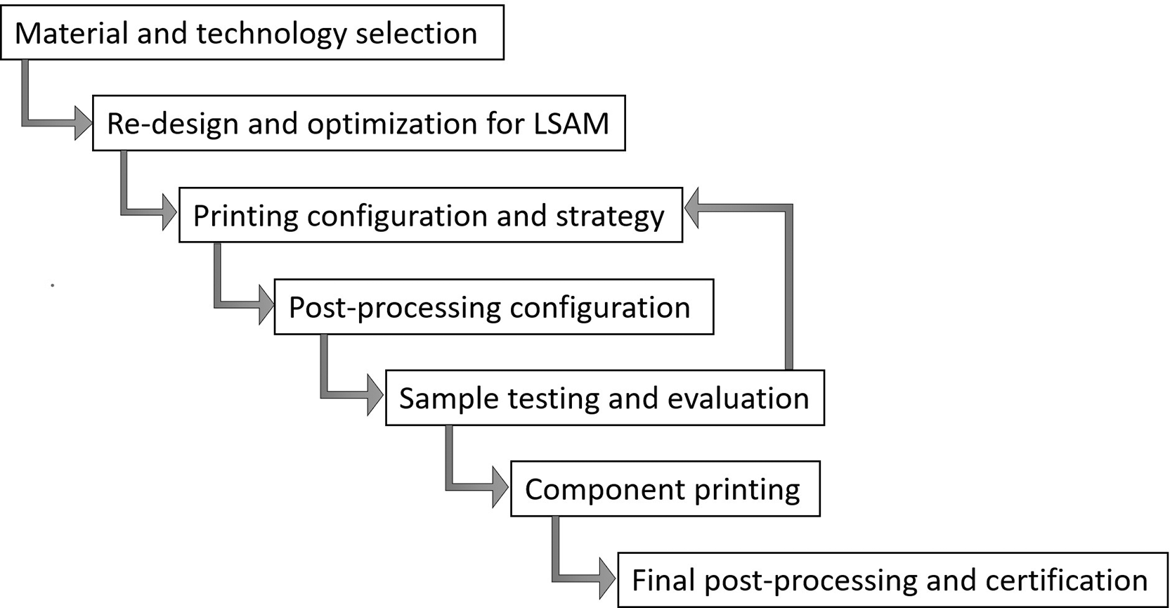
Figure 6. Recommended 7-step workflow for the Large-Format Additive Manufacturing of marine components, bridging the gap between digital design and class certification (Adapted from2).
8. Techno-economic and sustainability assessment
For LFAM to be adopted by WEC and TED developers alongside broader marine stakeholders, it must prove economically viable and environmentally superior against established materials like steel and GRP. The transition to additive manufacturing represents a fundamental shift in cost structures: moving away from labour-intensive and tooling-heavy traditional methods, towards machine-time, material, and energydriven models. This transition also fundamentally alters supply chain logistics, shifting value from physical inventory and transport towards digital design and localised, just-in-time production. Consequently, the R&I agenda mandates the rigorous tracking of specific techno-economic and sustainability metrics for LSAM parts. This quantitative analysis is essential to build a compelling business case, secure green financing, and make accurate cost predictions across the entire lifecycle of the marine asset.
8.1 Project-level cost prediction metrics
Accurately forecasting the financial viability of novel AM marine deployments compared to conventional offshore farms is a primary requirement for industry stakeholders. MRE projects are highly sensitive to initial capital outlays; therefore, demonstrating how LFAM reduces specific cost centres is critical.
The following formulas are required to be utilised to estimate macro-scale financial viability:
(1)
Where
Cdev represents device manufacturing costs,
CBoP is the balance of plant (moorings, cables),
Cinst covers installation,
CEPM is engineering and project management,
Clog is logistics,
Ccont is the contingency budget, and
Cdecom,res is allocated for decommissioning reserves. LFAM primarily targets the drastic reduction of
Cdev by eliminating mould fabrication and reducing assembly steps. Furthermore, the lightweight nature of topology-optimised polymer components directly decreases
Clog and
Cinst by reducing the required crane capacities and vessel sizes during offshore deployment.
(2)
To compare across technologies with different power ratings (
Pinst):
(3)
(4)
Where CF is the net capacity factor and L represents aggregated losses.
(5)
For preliminary assessments, the simplified LCOE utilising the Capital Recovery Factor (CRF) is to be used:
(6)
(7)
8.2 Part-level techno-economic metrics (shop floor)
Manufacturing massive marine components takes days, intersecting with fluctuating grid tariffs, machine depreciation rates, and requiring precise material forecasting. To precisely assess the cost of the 3D-printed component, manufacturing engineers must employ the following equations prior to initiating print jobs:
(8)
Where ρ is material density, Vsolid is the bounding volume, and finfill is the programmed infill percentage. By leveraging advanced slicing software, finfill can be dynamically varied throughout the part, placing dense material only where structural load paths dictate, thereby minimising mpart without sacrificing integrity. Furthermore, the “Buy-to-Use” ratio must be calculated, particularly for WAAM components requiring subtractive finishing, to account for the total raw material purchased (mraw) versus the final flying mass.
(9)
Where Cmat is the specific material cost, Rmachine is the hourly machine rate, and Cpost encompasses all secondary finishing and inspection operations cost. The Rmachine variable must carefully amortise the high initial capital investment of the robotic cell over its projected operational lifespan, factoring in maintenance and operator overheads.
(10)
(11)
Where
Eaux accounts for auxiliary operations like pellet drying, HVAC, and interpass cooling. It is important to note that
Eaux is highly sensitive to the manufacturing environment; operating in unconditioned shipyards may drastically increase the heating loads required to maintain optimal extrusion temperatures. For real-time energy assessment, direct power measurement is used:
Ejob =
(12)
Energy-intensive solid infill printing is required to be algorithmically scheduled to coincide with off-peak electricity grid tariffs. This approach can be further enhanced by synchronising production cycles with local renewable energy microgrids, executing high-draw operations when on-site solar or wind generation peaks.
8.3 Sustainability and carbon footprint assessment
The maritime sector is under strict regulatory pressure to decarbonise its supply chain. LFAM offers a pathway to sustainable manufacturing, but these claims must be quantified through standardised LCA methodologies. The total carbon footprint (CFtotal) of a printed marine component must be evaluated by aggregating the embodied carbon of the feedstock and the operational carbon of the manufacturing process:
(13)
Where EFmat is the emission factor of the raw material (kg CO2e/kg), EFgrid is the carbon intensity of the local electricity grid (kg CO2e/kWh), CFpost represents emissions from post-processing, and CFcircular represents the carbon credits gained by utilising recycled maritime plastics or end-of-life recyclability. The CFcircular term is particularly vital for the marine sector. By sourcing feedstock from end-of-life maritime assets—such as decommissioned GRP hulls or discarded fishing nets—manufacturers can claim significant carbon credits, transforming a waste management liability into a valuable resource.
8.4 Recommended assessment lifecycle
To ensure these metrics are accurately captured and utilised for continuous improvement, a three-phase quantitative assessment protocol is mandated:
•
Prior to Printing (Predictive Analysis): Utilise slicing software and digital twin simulations to forecast mpart, Tbuild, and Ejob. These predictive models allow engineers to perform cost-benefit analyses, comparing the projected LFAM CapEx and carbon footprint directly against traditional GRP or steel fabrication quotes before committing physical resources. This phase should also include sensitivity analyses to account for fluctuating raw material prices and grid tariffs.
•
During Printing (Real-Time Telemetry): Implement active monitoring of power draw (Pk) and material feed rates. This real-time data validates the SEC assumptions and ensures that dynamic energy cost scheduling is functioning correctly, allowing for mid-print adjustments if auxiliary systems consume more power than anticipated. Integrating this telemetry directly into shipyard Enterprise Resource Planning (ERP) systems ensures transparent cost tracking.
•
After Printing (Empirical Auditing): Conduct a final audit of the total consumed materials, actual machine hours, and post-processing labour. This empirical data is used to refine the predictive algorithms for future prints and to generate a certified Environmental Product Declaration (EPD) or “Digital Product Passport,” proving the component’s carbon footprint compliance to regulatory bodies and clients. This audit must also forecast end-of-life decommissioning, ensuring the printed material can be shredded and repelletised for future use.
9. Collaborative R&I agenda & future pathways
The successful industrialisation of Large-Format Additive Manufacturing within the marine and offshore sectors cannot be achieved in isolation. It requires a highly synchronised, cross-sectoral effort uniting naval architects, material scientists, robotic engineers, and maritime regulators. To transition from isolated laboratory successes to widespread commercial deployment, the industry must adhere to a structured, time-bound roadmap. Based on the foundational review of current technological bottlenecks and market demands, the following strategic Research & Innovation (R&I) pillars have been defined for the next 36 months. This agenda serves as a definitive blueprint to guide future investments, standardise methodologies, and ultimately de-risk the adoption of 3D-printed marine structures.
Table 3 outlines the R&I Action Plan and Responsibility Matrix. Such actions are defined based on main challenges identified in the present project and these are not meant to be exhaustive.
Table 3. R&I Action plan and responsibility matrix.
| Theme | Specific challenge | R&I Priority/Action item | Timeline |
|---|
| Material Durability
| Z-axis anisotropy and water absorption over a 20-year lifespan. | Long-term characterisation of printed polymers in seawater. Development of marine-specific protective sealants. | Months 1–12 |
| Geometrical Stability
| Warping of large, flat marine plates during LFAM. | Investigate fibre-reinforced composites and non-planar, thermal-optimised toolpaths to reduce residual stress. | Months 6–18 |
| Hydrodynamics
| High drag penalties caused by layer-induced surface roughness. | Develop automated, low-cost robotic finishing. Test non-planar toolpaths aligned with fluid streamlines. | Months 12–24 |
| Process Stability
| Real-time defect generation during unattended prints. | Integration of multi-sensor fusion (vision/thermal) and AI-driven closed-loop control for real-time defect correction. | Months 18–30 |
| Standardisation
| Lack of specific class-society rules for massive monolithic polymer WECs. | Establish robust “digital thread” protocols. Liaise with DNV/ABS to co-develop acceptable safety factors and NDT frameworks. | Months 24–36 |
| Circularity
| Environmental impact of virgin polymers. | Print functional WEC components using 100% recycled maritime plastics (circular economy). | Months 24–36 |
9.1 Integration with smart manufacturing and AI
Printing massive marine components often requires continuous, multi-day extrusion cycles. In such prolonged operations, a single uncorrected anomaly—such as a momentary drop in nozzle temperature, a partial nozzle clog, or a localised lack of fusion—can propagate through subsequent layers, ultimately ruining a component worth tens of thousands of euros. Currently, most LFAM systems rely on openloop control or passive monitoring, which merely alerts operators to a failure after it has occurred. To achieve the reliability required for maritime certification, the manufacturing paradigm must evolve towards autonomous, self-correcting systems.
Required Actions & Strategic Priorities: Future developments are required to shift from passive monitoring to active, Artificial Intelligence (AI)-driven quality assurance.
•
Multi-Sensor Fusion: Implement comprehensive sensor suites on the robotic end-effector, combining melt-pool thermal imaging, acoustic emission sensors (to detect micro-cracking), and laser profilometry (to verify bead geometry in real-time).
•
Closed-Loop AI Control: By utilising Convolutional Neural Networks (CNNs) and Reinforcement Learning (RL) algorithms trained on this multi-modal data, it is necessary for the LFAM robot to autonomously adjust critical parameters—such as travel speed, extrusion multipliers, and cooling fan intensity—in milliseconds to prevent voids and correct thermal deviations.10
•
Automated Compliance Logging: The AI system must automatically flag and record any parameter deviations that were successfully mitigated, directly generating the immutable “digital compliance logs” required by maritime regulators for part certification.
9.2 Hybrid routes and mobile LFAM
The sheer scale of marine structures presents a formidable logistical barrier. Transporting a 20-metre, multi-ton wave energy floater or tidal turbine blade from a centralised, inland manufacturing facility to a coastal deployment site involves exorbitant costs, specialised transport vehicles, and significant road infrastructure disruptions. Furthermore, traditional LFAM often struggles to achieve the strict geometric tolerances required for mechanical mating surfaces without transferring the massive part to a separate, equally large CNC machine.
Required Actions & Strategic Priorities: To bypass extreme logistical costs and streamline production, it is necessary to explore decentralised and hybrid manufacturing models.
•
Containerised Mobile LFAM: Develop and deploy mobile, weather-resilient LFAM robotic cells housed within standard shipping containers. This allows the manufacturing hardware to be shipped directly to shipyards, ports, and offshore hubs. This localised, just-in-time manufacturing model will radically alter the offshore supply chain, eliminating heavy transport costs.
•
Digital Warehousing: Transition from physical spare parts inventories to “digital warehouses.” Marine operators will be able to download certified CAD files and print replacement components, modular floater upgrades, or custom tooling directly on-site, drastically reducing vessel downtime.
•
All-in-One Hybrid Cells: Implement hybrid robotic end-effectors equipped with automatic tool changers. This allows a single robotic arm to deposit material rapidly via pellet extrusion or WAAM, and subsequently switch to a subtractive milling head to machine critical flanges and hydrodynamic surfaces to precise tolerances, all within the same setup.
9.3 Proposed major milestones for industrialisation
To ensure the R&I agenda remains focused and accountable, the following major milestones are proposed to guide the industry’s trajectory over the next three years:
•
Milestone 1 (Months 1–12): Material Qualification & Digital Twin Validation. Complete the accelerated seawater ageing and fatigue testing of chosen composite feedstocks. Successfully validate the thermo-mechanical digital twin software by accurately predicting and mitigating warpage on a 2-metre scale test panel.
•
Milestone 2 (Months 13–24): Sub-Scale Functional Prototypes & AI Integration. Manufacture a 1:3 scale functional marine device (e.g., a WEC floater) utilising closed-loop AI control. Demonstrate automated hybrid finishing on the component’s hydrodynamic surfaces and successfully test the prototype in a controlled wave basin environment.
•
Milestone 3 (Months 25–36): Full-Scale Offshore Deployment & Class Certification. Deploy a full-scale, LFAM-manufactured primary loadbearing structure in an open-water offshore test site. Concurrently, achieve formal “Approval in Principle” (AiP) from a major classification society (e.g., DNV or ABS) by submitting the physical part alongside its complete, AIgenerated digital thread.
10. Conclusion
The transition toward Large-Format Additive Manufacturing represents a critical enabler for the commercial viability and sustainability of new marine green technology and existing marine components. As outlined in this R&I Agenda, moving away from labour-intensive, tooling-heavy traditional manufacturing towards an agile, digital, and tool-less paradigm is essential to overcome the historical bottlenecks of the marine domain. This document provides the structural blueprint for the project, its partners and stakeholders to navigate this complex technological shift.
By systematically addressing the unique structural and regulatory constraints of the ocean environment, this agenda has identified targeted strategies to deal with extreme hydrodynamic loading, slamming, and corrosion-fatigue. The integration of advanced computational modelling, topology optimisation, and non-planar robotic kinematics ensures that LFAM can produce highly complex, hydrodynamically efficient geometries that are impossible to achieve via conventional methods.2 Furthermore, the proactive mitigation of inherent AM challenges—such as Z-axis anisotropy, thermal warpage in large flat plates, and the “stair-stepping” surface roughness penalties—has been thoroughly detailed through material compounding, intelligent toolpathing, and automated hybrid finishing.
Crucially, this agenda establishes an essential, 7-step manufacturing workflow designed to bridge the gap between functional prototyping and class certification. By aligning with emerging guidelines from major classification societies and mandating the creation of an immutable “digital thread” via multi-sensor fusion and AI-driven closed-loop control, the groundwork is laid for goal-based regulatory approval. This digital traceability is paired with comprehensive techno-economic and sustainability metrics, ensuring that CapEx, OpEx, and carbon footprint reductions are accurately predicted, monitored, and empirically audited.
Looking forward, the strategic R&I pillars defined for the next 36 months will drive the industrialisation of additive marine structures. The exploration of circular feedstocks, such as upcycled maritime plastics, alongside the deployment of mobile, containerised LFAM units directly at shipyards, promises to radically decentralise the offshore supply chain. By executing the milestones and methodologies outlined herein, LFAM will successfully transition from a prototyping novelty into a certified, scalable, and highly sustainable pillar of global marine manufacturing.
Disclaimer
Funded by the European Union. Views and opinions expressed are however those of the author(s) only and do not necessarily reflect those of the European Union or the European Research Executive Agency (REA). Neither the European Union nor the granting authority can be held responsible for them.
Declaration of generative AI and AI-assisted technologies in the writing process
During the preparation of this document, the author utilized the Google AI Studio platform powered by the Gemini Pro 3.1 Large Language Model (LLM) to improve the overall structure, refine the English language, and perform grammar checks. Following the use of this tool, the author carefully reviewed and verified all generated outputs in every instance to prevent inaccuracies or erroneous data. The author takes full responsibility for the final content and integrity of this agenda.
Data availability
All data underlying the results are available as part of the article and no additional source data are required.
Acknowledgements
The author would like to express sincere gratitude to Giuseppe Giorgi and Giuliana Mattiazzo (Politecnico di Torino), Giovanni Avallone (Caracol AM), Paulo Rosa-Santos and Francisco Taveira-Pinto (University of Porto and CIIMAR) for their invaluable support throughout this project. Their mentorship, assistance in funding acquisition, and insightful discussions have been instrumental in shaping the general ideas and strategic direction presented in this agenda.
References
- 1.
Rubino F, Nistico` A, Tucci F, et al.:
Marine Application of Fiber Reinforced Composites: A Review.
J. Mar. Sci. Eng.
2020; 8(1): 26. Publisher Full Text
- 2.
Giannini G, Giorgi G, Mattiazzo G, et al.:
Toward Scalable and Sustainable Manufacturing Solutions – A Review of Large-Format Additive Manufacturing for Marine Applications with Recommended Methods and Materials.
Appl. Ocean Res.
2026; 173: 105122. Publisher Full Text
Reference Source
- 3.
Sabic C:
Enabling Growth for Pellet-fed Additive Manufacturing.2022.
Reference Source
- 4.
Henao Y, et al.:
Wind turbine blade repurposing and recycling: Coupling repurposing methods with 3D printing technology.
Proceedings of the International Conference on Non-conventional Materials and Technologies (NOCMAT).
2023.
- 5.
Aravind A, Jerome S, Kumar R;
Evaluation on Mechanical and Metallurgical Properties of Wire Arc Additive Manufactured ER 2209 Duplex Stainless Steel for Automotive and Marine Applications. SAE Technical Paper.2025.
- 6.
Cheng G, et al.:
Investigation of high-cycle fatigue properties of wire arc additive manufacturing 13Cr4Ni martensitic stainless steel.
Metals.
2023; 13(7): 1210. Publisher Full Text
- 7.
Alsaadi M, Flanagan T, Devine DM:
Seawater ageing effects on the mechanical performance of basalt fibre-reinforced thermoplastic and epoxy composites.
J. Compos. Sci.
2025; 9(7): 368. Publisher Full Text
- 8.
Ye L, et al.:
Review of online quality control for laser directed energy deposition (LDED) additive manufacturing.
Int. J. Extreme Manuf.
2025; 7(6): 062005. Publisher Full Text
- 9.
Chen H, et al.:
Electricity use in big area additive manufacturing of fiber-reinforced polymer composites.
Sci. Data.
2024; 11: 1362. Publisher Full Text
- 10.
Schurmann M, et al.:
A framework for in-situ process control in metal additive manufacturing using anomaly-driven reinforcement learning.
Procedia CIRP.
2025; 134: 211–216. Publisher Full Text
- 11.
Brenken B, Barocio E, Favaloro A, et al.:
Fused filament fabrication of fiber-reinforced polymers: A review.
Addit. Manuf.
2018; 21: 1–16. Publisher Full Text
- 12.
Zhang Y, Chou K, Sealy MP:
Thermal-mechanical modeling of residual stress and distortion in large-format additive manufacturing.
Addit. Manuf.
2021; 46: 102125.
- 13.
Duty C, et al.:
Structure and mechanical behavior of Big Area Additive Manufacturing (BAAM) materials.
Rapid Prototyp. J.
2017; 23(1): 181–189. Publisher Full Text
- 14.
Talagani M, et al.:
Numerical simulation of big area additive manufacturing (3D printing) of a full size car.
SAMPE J.
2015; 51(4): 27–36.
- 15.
Kishore V, et al.:
Infrared preheating to improve interlayer strength of big area additive manufacturing (BAAM) components.
Addit. Manuf.
2017; 14: 7–12. Publisher Full Text
- 16.
Compton BG, Lewis JA:
3D-printing of lightweight cellular composites.
Adv. Mater.
2014; 26(34): 5930–5935. Publisher Full Text









