1. Introduction
Owing to continuous technological progress and the rapid expansion of electrification, the application scope of LIMs has increased significantly in recent years. These machines are increasingly deployed in industrial automation, transportation systems, renewable energy infrastructure, and other demanding applications where high reliability and operational stability are required.1–3 Consequently, LIMs are often exposed to harsh operating environments involving elevated mechanical and thermal stress, leading to intensified loading conditions and stricter performance requirements. This trend has created a growing need to improve the mechanical durability of the secondary element while simultaneously enhancing its electrical and magnetic characteristics.
Traditionally, high-performance electric machines have relied on permanent magnet technologies that depend on critical raw materials (CRMs), particularly rare-earth elements such as neodymium and dysprosium. While these materials enable high efficiency and torque density, their extraction and processing are associated with significant environmental impacts, including water contamination, hazardous waste generation, and high energy consumption. In addition, global supply chains for rare-earth elements remain geographically concentrated, creating economic and geopolitical vulnerabilities.4 As a result, increasing attention is being directed toward the development of rare-earth-free electric machine technologies capable of achieving comparable performance while reducing dependence on CRMs.
Within this context, induction motors represent a promising alternative due to their robustness, scalability, and relatively simple construction. However, achieving higher efficiency and improved electromagnetic performance requires optimization of the rotor and secondary element properties. These characteristics are strongly linked to the properties of the materials used and to the surface quality of the secondary element. Therefore, more stringent requirements are imposed on the base materials, their parameters, and their functional performance. To meet modern operational and sustainability requirements, the surface of the secondary element must therefore exhibit optimized mechanical, electrical, and magnetic properties while also supporting lifecycle sustainability and resource efficiency objectives.
Recent studies indicate that copper-coated iron structures can provide an effective balance between magnetic permeability and electrical conductivity, enabling reduced eddy current losses, improved thermal stability, and enhanced thrust characteristics..5 Currently, various copper-deposition techniques are known,6 including electroplating and cold spray deposition, which allow the production of high-quality coatings. To improve the electromagnetic parameters of electric machines, copper-coated secondary elements with different coating thicknesses are employed. These coatings form an additional conductive path in the LIM equivalent circuit and enable achieving specific electrical resistivity and magnetic permeability within the desired range.7 These parameters directly influence the starting and operational characteristics of LIMs. Such motors can be used in transportation systems to improve their performance, particularly in high-speed rail transportation systems.
Previous research has demonstrated the potential benefits of copper-coated iron secondary elements for enhancing the electromagnetic performance of linear induction motors. However, the relationship between copper coating thickness and LIM performance has not been comprehensively quantified. In particular, the influence of coating thickness on key operating parameters, including efficiency, power factor, and overall machine performance, remains insufficiently understood. This study therefore aims to investigate the potential of copper-coated solid secondary elements for improving the electromagnetic and mechanical performance of LIMs, while also evaluating their applicability as a rare-earth-free alternative to conventional high-performance motor technologies. Particular attention is given to the effect of copper coating thickness on performance enhancement from the perspective of sustainable and resource-efficient electric machine design.
2. Literature review
In modern urban and intercity rail transport systems, numerous applications of linear electric drives have been developed and implemented. Among them, particular attention is given to LIMs and linear synchronous motors (LSMs) with permanent magnets.8,9 Depending on operational requirements and application conditions, both motor types are successfully employed in railway systems of varying purposes, structures, and speed ranges, including both low-speed and high-speed transport.8–10 Resent research in that field is focused on improving their design and operating parameters for transportation8,9 as well as for broader industrial applications.11
In the context of maglev transportation systems, both LIM and LSM drives present distinct advantages and limitations.8–10 Although LSM-based propulsion systems require a more expensive guideway infrastructure, they remain one of the preferred practical solutions for high-speed operation (exceeding 200 km/h).8–10 In contrast, LIM systems face increasing challenges at high speeds due to the weight and complexity of onboard power conditioning equipment, as well as difficulties in transferring high electrical power efficiently.8,9 However, at lower speeds (≤100 km/h), LIM drives have demonstrated reliable and cost-effective all-weather performance in both maglev and conventional steel-wheel railway systems. For intermediate speeds around 200 km/h, the selection between LIM and LSM technologies depends largely on lifecycle cost considerations.8,9 LIM technology benefits from its similarity to conventional rotary motor systems widely used in railways, enabling easier integration and leveraging existing engineering experience. Additionally, LIM systems feature relatively simple guideway constructions, resulting in lower infrastructure costs, reduced maintenance requirements, and high operational flexibility. Although LIM systems generally exhibit lower efficiency and power factor compared to LSM systems, recent research is focused on reducing this gap.8,9
One of the specifications of LSMs is permanent magnet LSM (PM-LSM). Permanent magnets have been widely applied in LSMs, particularly in industrial automation and transportation systems. Their use in urban maglev propulsion is also expanding.8,9 Advances in rare-earth magnetic materials, especially neodymium-iron-boron (Nd-Fe-B) and samarium-cobalt (Sm-Co), have enabled high-performance motor designs due to their high magnetic energy density, strong remanent magnetization, and high coercivity. Transportation systems based on PM-LSMs are characterized by high efficiency and high thrust force, making them suitable for high-speed applications.8,9 Their control systems are analogous to those used in conventional rotary synchronous motors, allowing the reuse of established servo control technologies.9 Structurally, PM-LSMs resemble linear pulse motors and may be considered a specialized form within this class. However, such systems are typically designed for specific applications rather than standardized deployment. Nowadays, certain successes are known in the implementation of PM-LSMs in high-speed transport systems and studies of improving their construction.8–10 However, compared with LIMs complex construction of transportation systems with PM-LSMs remains one of the important engineering challenges.9,10 Robust support and fixation structures are necessary to withstand strong magnetic forces. Furthermore, environmental factors such as temperature variations and corrosion also should be considered. Especially permanent magnets need protective measures from environmental factors, which may reduce magnetic performance.9 Besides, the requirement for larger permanent magnet components complicates magnet manufacturing, particularly achieving uniform magnetization, and increases mechanical stresses within the system. As a result, the initial investment for PM-LSM-based systems remains relatively high, particularly due to the specialized nature and limited production scale of large rare-earth magnet components.9 From an environmental and sustainability perspective, the use of PM-LSMs also presents challenges. These include the environmental impact of rare-earth material extraction, processing difficulties, and the limited geographical distribution of key resources, which are concentrated in a small number of countries.12,13
An important application of copper coating is in induction motors. Of particular interest are the solid rotors of rotating induction motors and secondary elements of the LIMs (
Figure 1). As shown in,5 in transport LIMs, copper-coated secondary elements are used to enhance the electromagnetic coupling between the primary and secondary circuits, thereby improving electromagnetic parameters.5 One approach to structural improvement of electrical machines has been proposed in.14 In,14 a method for manufacturing stacked magnetic cores for electrical machines is presented, in which, for the reliability of the magnetic core attachment, the assembly of the stack is implemented using uniform metal coating deposition by spraying.14 Copper coating can be applied to ensure high speeds in rotating induction motors.15 Copper plating can increase output power and reduce the rotor resistance.7
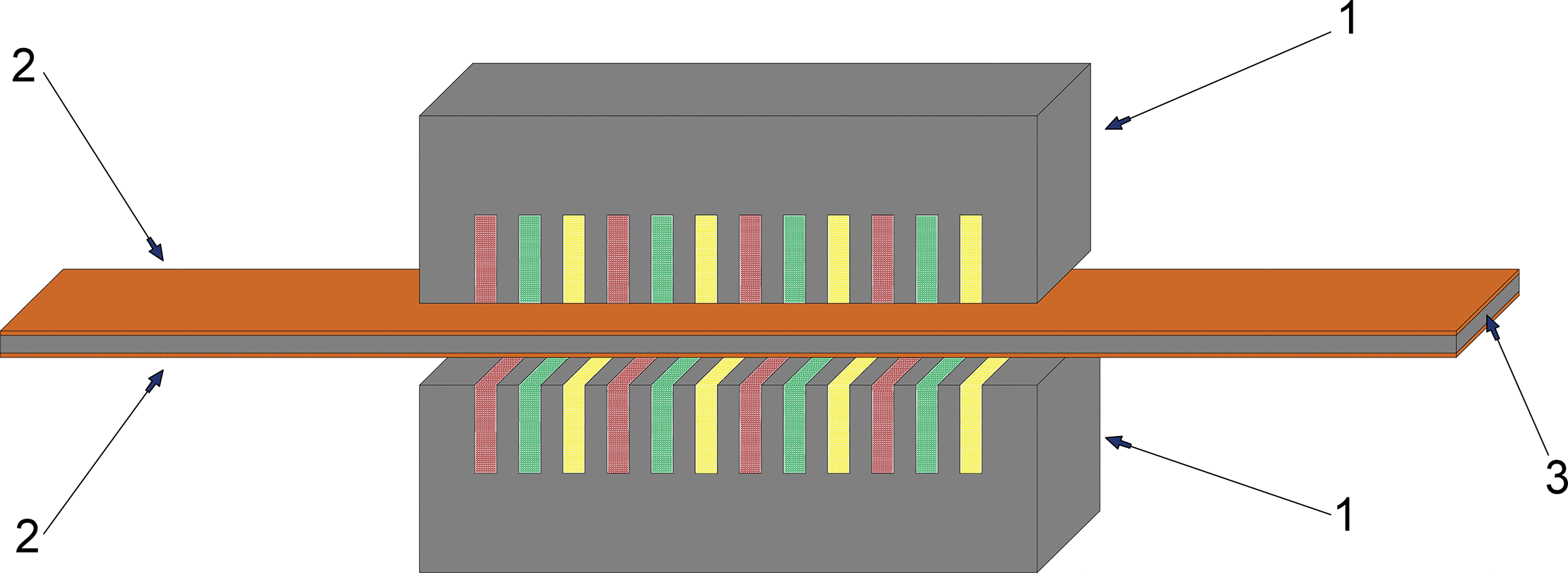
Figure 1. Top view of a double-sided LIM with a copper-plated solid secondary element. 1. Double-sided stator with a three-phase winding. 2. Copper layer. 3. Solid iron secondary element.
The double-sided LIM consists of a short stator and a long secondary element. The secondary element is made of solid iron and is copper-plated on both sides. The stator incorporates a three-phase winding that produces the travelling magnetic field. Each phase winding was represented by a single color.
Currently, significant research attention is focused on LIMs with copper-coated secondary elements.16–19 These studies aim to improve the electromagnetic and mechanical characteristics of motors.
Table 1. presents LIM configurations with iron secondary elements of varying thickness (iron thickness - ∆h) coated with copper layer (copper layer thickness - ∆Cu).
Table 1. Variants of LIM with copper-plated secondary element.
| Motor type | Specification of secondary element |
|---|
| LIM16 | Flat steel magnetic core ∆h = 8 mm with ∆Cu = 2 mm copper layer |
| LIM17 | Flat steel magnetic core with ∆Cu = 5 mm and ∆Cu = 10 mm copper layers |
| LIM18 | Magnetic core ∆h = 6 mm made of three 2 mm thick steel plates
(St-3), copper-plated with ∆Cu = 3 mm layer |
| LIM19 | Flat steel magnetic core ∆h = 8 mm with ∆Cu = 3 mm copper layer |
Studies16–19 focus on improving the thrust force, power factor, and efficiency (η) of LIM. Although the listed LIMs have different nominal powers, thrust forces, and dimensions, the objectives of improving these parameters can be achieved by copper plating the secondary element.16–19
Currently, several methods for applying metal coatings to the surface are known, such as cladding, plating, and spraying techniques. These methods are further subdivided depending on the application and properties of the material. In recent years, additive manufacturing-based coating methods have also been actively utilized.6,20
It is worthwhile to consider the method of galvanic copper deposition separately. This method represents an electrochemical process of applying a copper coating to a surface.21 One limitation of this method is the potential for non-uniform thickness distribution of the deposited coating across the surface.21 More uniformity in the coating can be achieved by using additional anodes and shielding elements, as well as by utilizing the «throwing power» (ability of the electrolyte to produce uniform coatings) of the electrolyte, which depends on the electrolyte’s electrical conductivity and polarization characteristics.21
Depending on the application, the listed methods are successfully used to obtain coatings for various purposes. In addressing the objective, it is important that the microstructure and properties of both the coating material and the substrate remain as unchanged as possible. In addition, internal stresses and deformations in the product must be avoided and the coating process should be technologically simple, easy to implement and suitable for use under field conditions. A method that best satisfies these requirements is cold gas dynamic spray (CGDS).22,23 CGDS is a type of gas-dynamic spraying, the essence of which lies in accelerating particles of powdered material in a carrier gas to supersonic speeds using a Laval nozzle or its modifications. The particles, accelerated by the gas flow, impact with the treated surface and adhere to it. Pure ductile metals, as well as mechanical mixtures of metallic, ceramic, or polymer powders, can be used for coating deposition. In the CGDS process, particle velocity is mainly controlled by adjusting the gas pressure, while the gas temperature varies within a limited range and remains significantly below the melting temperature of the particles, preventing melting and excessive heating of the substrate. It is important to note that, compared with other technologies, the CGDS method has several significant advantages:
• The coating application process does not induce significant thermal effects in the substrate. As a result, internal stresses, deformations, and changes in mechanical properties are minimized or eliminated.
• During the coating deposition, the surface is cleaned of technical contaminants, oils, and paints, which facilitates an improved coating process.
• Coatings can be applied to localized areas of the surface.
Coatings can be deposited under both stationary and field conditions, in ambient air at atmospheric pressure, and the process is relatively environmentally friendly.6,22–25
From a chemical perspective, CGDS coating technique has significant advantages due to its solid-state nature.26–28 In contrast to conventional thermal spraying, which relies on high temperatures, cold spray operates below the melting point of the feedstock material,26,27 preventing oxidation, decomposition, and undesirable phase transformations while preserving chemical purity and much of the original microstructure.26,29 This is especially important for metals prone to oxidation, such as copper.30,31 The relatively low processing temperature also limits thermal interaction with the substrate, thereby reducing the likelihood of heat-affected zones, excessive diffusion, residual stress development, and microstructural changes,28,32 making the technique suitable for temperature-sensitive components and multilayer systems.
From an environmental perspective, cold spray can be considered a relatively cleaner and more sustainable alternative to other coating technologies.28,32 The process operates without combustion or plasma generation, thereby avoiding significant emissions such as nitrogen oxides (NOx), volatile organic compounds (VOCs), and carbon monoxide (CO), which are typical of thermal spraying and electroplating processes.28,32 It also reduces material waste through efficient particle delivery, enabling powder recycling and minimizing overspray, while enclosed operation limits worker exposure to hazardous substances and airborne particles, improving occupational safety and reducing environmental and health impacts.32 However, the process is not inherently low in energy consumption, as it requires high-pressure gases and powerful compressors to accelerate particles to supersonic speeds,27,32 and in some cases, depending on system, may demand more energy than conventional thermal spray methods. Nevertheless, the absence of combustion and molten materials eliminates fuel-related emissions and reduces the need for extensive post-processing or fume extraction systems.28,32
The chemical behavior of copper under cold spray conditions makes it an excellent candidate for applications requiring high electrical and thermal conductivity.30 Due to the solid-state nature of the process, oxidation is significantly limited compared to thermal spraying, resulting in substantially lower oxygen contents in cold-sprayed copper coatings.30 During deposition, copper particles undergo severe plastic deformation upon high-velocity impact, forming dense coatings through solid-state metallic bonding without melting, which minimizes oxidation and porosity while enabling high electrical conductivity.29–31 Copper is also a recyclable and relatively abundant material, and cold spray enables its efficient utilization while minimizing waste.32 Furthermore, the process eliminates the need for chemical etching, electroplating baths, and hazardous solvents, significantly reducing environmental impact compared to conventional methods that involve heavy metal ions and generate toxic sludge.28,32
Taking into account the above considerations, LIMs with copper coated secondary elements can be regarded as a promising solution for railway transportation systems. In addition to offering competitive performance and cost advantages, such systems avoid the use of rare-earth materials, thereby mitigating environmental concerns, supply risks, and resource concentration issues associated with permanent magnet technologies.
Existing studies on copper coatings discuss that such coatings may improve the electromagnetic characteristics of LIMs while also enhancing the functional properties of coating systems, including composite coating applications.6,23,33,34 In these cases, the copper layer may act as the primary surface exposed to corrosion, wear, and environmental effects, while remaining relatively easy to restore or replace. In LIMs, wear may occur on secondary elements operating under conditions of mechanical interaction and aggressive environmental exposure. When a copper-coated secondary element is used, degradation primarily affects the copper layer, which functions as a replaceable surface. Restoration of the copper coating may be technologically simpler and more cost-effective than manufacturing a new iron secondary element, potentially reducing maintenance costs and improving system durability and maintainability. Furthermore, the mobility and technological flexibility of CGDS systems enable local restoration of conductive surfaces and geometric dimensions, which may be beneficial for transport infrastructure maintenance and for small-sized LIM applications where structural modifications are limited.
3. Materials and methods
Improving the quality, reliability, and electromagnetic performance of LIMs remains an important objective. For coating the secondary element, both the selection of the coating material and precise control of the deposition thickness at the sub-millimeter scale are critical. This is primarily due to the influence of the coating layer on the electrical and magnetic parameters of the LIM. In addition, non-uniform thickness of the deposited layer may lead to significant distortion of the magnetic field, when the motor operates with small air gaps. Considering these factors and literature review results, copper was selected as the coating material for the solid iron secondary element of the LIM. The selection was determined by the combination of high electrical and thermal conductivity, good ductility, favorable adhesion to metallic substrates, and the possibility of depositing relatively thick conductive layers.21 In addition, the CGDS method was chosen as the deposition technique due to its limited thermal impact on the substrate, low oxidation level, and suitability for applying conductive coatings with controlled thickness.
To evaluate the impact of applying a copper coating, new additional calculations were performed based on previous research methodology.35 The secondary element parameters of the LIM were determined analytically using the corrected Г-shaped replacement equivalent circuit scheme of an induction motor with a solid secondary element.36 This approach is based on the concept of complex magnetic resistance, which depends on the electrical conductivity of the magnetic circuit, magnetic permeability, frequency, and geometrical parameters.36 Тhe presence of the copper layer was incorporated into the equivalent circuit, as described in.35 Specifically, an additional parallel branch was introduced in the secondary circuit to represent the active resistance of the copper coating, while the reactance of the coating was neglected.35 The calculation procedure follows established methodologies from,35,37 where37 addresses LIMs with solid secondary elements, while35 analyses the composite secondary elements with a copper coating. End effects and mechanical aspects were not considered in the calculations.
The LIM parameters and performance characteristics were calculated analytically according to the following procedure:
• calculating the stator parameters based on the initial conditions,
• determining the active and reactive resistances of the secondary element using the complex magnetic resistance approach,
• determination of the LIM operating parameters and performance characteristics using the equations (1–9) and the procedures described in Annex 1.38
The stator parameters were calculated using standard methods based on the Г shape equivalent circuit schemes of induction motors as described in classical machine theory.39 Calculations of losses and efficiency were carried out using the principles and equations presented in,37 while the parameters of the secondary element, thrust force, and critical slip were determined based on the complex magnetic resistance approach described in.35,36 The thrust force was determined:
(1)
where
is the critical slip, which can be calculated:
(2)
where
r2 is the equivalent active resistance of the secondary element referred to the stator and its values are provided in,
35 FTcr is the critical thrust force and
q, h are coefficients which are related to stator and rotor active and reactive resistance and taken from the theory of complex magnetic resistance. All these parameters were determined using the complex magnetic resistance approach described in.
35,36 The
σ is the correction factor, which can be calculated from:
(3)
Where r1 and x1 active and reactive resistances of the stator winding, and xμ magnetic reactance of air gap and was calculated using the following equation:
(4)
where
m is the number of stator phases,
fs supply frequency,
p number of pole pairs,
τ pole pitch,
lδ width of stator,
δ air gap,
W1 is the number of turns in the stator winding,
kμ,
kδ and
kw are saturation, air gap and winding coefficients respectively. These parameters and
r1 and
x1 active and reactive resistances, as described earlier are calculated using the classical equivalent circuit scheme of electrical machines.
5,39The operating slip was determined by solving the equivalent circuit equations under the condition of nominal stator current, whereas the power factor and the linear velocity of the vehicle were determined using established methods reported in.7,36,39 The operating slip was determined at the rated stator current from the stator current-slip characteristic. According to the equivalent circuit36,39 of the induction motor, the stator current can also be expressed as the phasor sum:
(5)
Where Iμ is the magnetizing current and I2’ is the secondary current referred to the stator, which was evaluated using approach described in.39
The stator current magnitude is represented as a vector sum of its active and reactive components:
(6)
Where I1a and I1x are the active and reactive components of the stator current, respectively. The power factor is determined as:
(7)
Linear velocity of the vehicle is defined as:
(8)
Where vs is the synchronous velocity of the magnetic field and sop is the operating slip of the LIM. Efficiency of the LIM can be calculated:
(9)
Where FTop and vop are the operating thrust force of the LIM and velocity of vehicle. ∑P is the summary of losses of the LIM, which can be evaluated according to approach described in the.37 ∑P include stator winding and iron core losses, secondary element losses and additional losses which include mechanical and additional magnetic losses.
The described methodology was applied to a practical case study. The calculations were performed for a LIM designed for a railway transportation system. This allows assessing how the copper coating improves electromagnetic coupling and overall motor performance. LIM configuration was selected with a double-sided short stator and a long secondary element (
Figure 1). Carbon structural steel (Steel-3) was selected as the material of the solid secondary element, both without coating and with copper coatings of various thicknesses (∆Cu). The stator parameters were kept identical for all evaluated cases, while the copper-layer thickness ∆Cu, was varied within the range of 0–0.002 m, the range of which is based on calculations reported in.35 In addition, the stator winding was designed with a three-phase star connection. The stator core was manufactured from grade 2013 electrical steel laminations. The stator was mounted on the moving vehicle, whereas the secondary element remained stationary.
Since the LIMs under consideration are analyzed from the point of view of their application in transportation systems, the results of studies of LIMs used in transportation systems for various purposes were taken into account when choosing the initial conditions of the LIM with a copper-coated solid secondary element.5,8,40,41 In contrast to the previous study,35 which primarily focused on the parameters of the secondary element and the thrust force of the LIM, the present work evaluates an extended set of LIM characteristics. In particular, operating slip, critical slip, thrust force, linear velocity of the vehicle, power factor, and efficiency are determined based on the equivalent circuit parameters under steady-state operating conditions. The copper-layer thickness is treated as a variable parameter influencing the electromagnetic characteristics of the system. The complete numerical dataset, including the input parameters and calculation results, is provided in Annex 2.42 The initial parameters of the LIM are presented in
Table 2.
Table 2. Initial conditions of the LIM.
| LIM parameter | Symbol | Unit |
Value |
|---|
| Initial conditions |
| Thrust force |
| N | 5000 |
| Linear speed of traveling magnetic field |
| m/s | 10 |
| Air gap |
| m | 0.002 |
| Vehicle mass | M
| kg | 5000 |
| Stator length | l
| m | 1 |
| Supply frequency |
| Hz | 50 |
| Supply phase voltage |
|
| 220 |
| Number of stator modules |
| - | 2 |
| Number of winding phases |
| - | 3 |
4. Results and discussion
The parameters were calculated sequentially in accordance with the procedure described in the methods section and,35–38 starting from equivalent circuit parameter identification and proceeding to force, slip, and performance evaluation. The calculated parameters of the investigated LIMs stator are summarized in
Table 3.
Table 3. Calculated parameters of the LIM.
| LIM parameter | Symbol | Unit |
Value |
|---|
| Calculated parameters |
| System power |
| kW | 72.6 |
| Pole pitch |
| m | 0.1 |
| Number of pole pairs |
| - | 5 |
| Effective core length |
| m | 0.1 |
| The rated current of the traveling field winding section |
| A | 54.99 |
| Active resistance of the phase winding |
| Ohm | 0.111 |
| Reactive resistance of the phase winding |
| Ohm | 0.409 |
| Slot width |
| m | 0.0167 |
| Slot height |
| m | 0.0448 |
| Air gap magnetic flux density |
| T | 1.1 |
| Total number of slots |
| - | 30 |
| Number of turns per phase |
| - | 145 |
| Active resistance of the iron secondary element |
| Ohm | 1.28 |
| Reactive resistance of the secondary element |
| Ohm | 0.768 |
Table 4. presents the calculated operating slips (sop), thrust forces (FTop), linear speeds of vehicle (vop), power factors (cosφop), efficiencies (ηop), and critical slips (scr) of the LIM.
Table 4. Parameters of the LIM with and without a copper-coated secondary element.
|
m | Parameters of LIM |
|---|
|
|
|
, N |
, m/s |
|
|
|---|
| 0 (St-3) | 13.53 | 0.518 | 2335.6 | 4.82 | 0.534 | 0.391 |
| 0.0001 | 13.47 | 0.513 | 2333.7 | 4.86 | 0.534 | 0.392 |
| 0.0002 | 13.43 | 0.514 | 2344.2 | 4.85 | 0.535 | 0.392 |
| 0.0004 | 13.33 | 0.512 | 2352.3 | 4.88 | 0.536 | 0.393 |
| 0.0005 | 13.28 | 0.507 | 2349.7 | 4.93 | 0.536 | 0.394 |
| 0.0006 | 13.23 | 0.508 | 2360.4 | 4.92 | 0.537 | 0.394 |
| 0.0008 | 13.13 | 0.505 | 2368.3 | 4.95 | 0.538 | 0.396 |
| 0.001 | 13.03 | 0.502 | 2376.1 | 4.98 | 0.538 | 0.397 |
| 0.0015 | 12.79 | 0.491 | 2387.8 | 5.08 | 0.539 | 0.401 |
| 0.002 | 12.56 | 0.486 | 2411.9 | 5.14 | 0.542 | 0.404 |
As shown in
Table 4, compared with an LIM using a solid iron secondary element (∆Cu = 0), increasing the copper-layer thickness of the copper-coated secondary element results in a decrease in critical and operating slips from 0.443% to 7.17% and from 0.77% to 6.18%, respectively. At the same time, operating velocity and efficiency increased from 0.83% to 6.64% and from 0.255% to 3.32%, respectively. The operating power factor also shows a slight increase, from 0.534 to 0.542, corresponding to an overall increase of approximately 1.49%. (
Figure 2,
Figure 3).
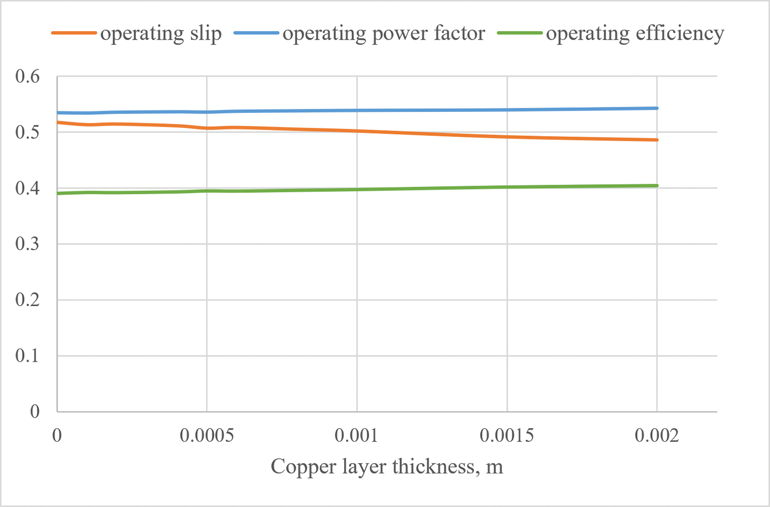
Figure 2. Dependence of operating slip (sop), power factor (cosφop) and efficiency (ηop) on copper layer thickness ∆Cu.
The figure shows the dependence of the operating slip, power factor, and efficiency on the copper layer thickness. The case of ∆Cu = 0 corresponds to a solid secondary element without a copper coating. The copper layer thickness varies over the range from 0.0001 m to 0.002 m using the following values: 0.0001, 0.0002, 0.0004, 0.0005, 0.0006, 0.0008, 0.0010, 0.0015, and 0.002 m. The figure illustrates the variation of the operating parameters with increasing copper layer thickness. The values for graph are taken from
Table 4.
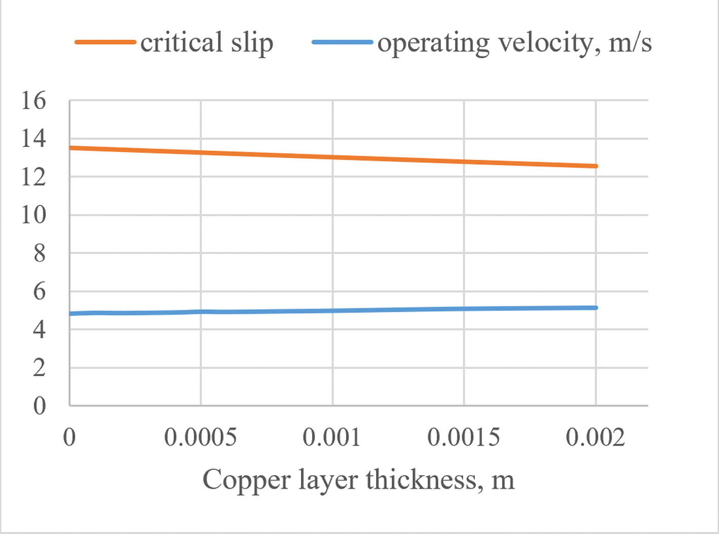
Figure 3. Dependence of operating velocity of vehicle (vop) and critical slip (scr) on copper layer thickness ∆Cu.
The figure shows the dependence of the operating velocity of the vehicle and the critical slip on the copper layer thickness. The figure illustrates how the operating velocity and critical slip vary with increasing copper layer thickness. The values of graph were demonstrated in
Table 4. and the copper layer thickness varies from 0.0001 m to 0.002 m using the same discrete thickness values as those considered in
Figure 2.
According to the operational thrust force results presented in
Table 4, compared with the LIM using a solid iron secondary element (baseline value: ∆Cu = 0), the introduction of a copper layer initially results in a 0.08% decrease in thrust force, with the minimum value observed at ∆Cu = 0.0001 m. With a further increase in copper layer thickness, the thrust force generally increases, reaching its maximum value at 0.002 m, corresponding to an increase of approximately 3.27% relative to the baseline value (
Figure 4). A minor local decrease in thrust force is observed between ∆Cu = 0.0004 m and 0.0005 m, where the thrust force decreases from 2352.3 N to 2349.7 N, corresponding to approximately 0.11%. This small variation does not alter the general tendency of increasing thrust force with copper layer thickness. The observed increase in thrust force may be associated with changes in the effective conductivity of the secondary element, current redistribution and changes in the interaction between the magnetic field and the secondary element. The initial decrease in thrust force followed by its subsequent increase with increasing copper-layer thickness requires further investigation. As shown in,43 the skin depth of an electromagnetic wave in copper at 50 Hz is on the order of centimeters and decreases with increasing frequency. The field amplitude inside a conductor decays exponentially with depth. In practical applications, the effective penetration depth may be smaller than the theoretical value due to material properties and non-ideal conditions.43 Although the skin depth exceeds the coating thickness, the mechanism underlying the observed thrust force trend requires further investigation and FEM validation.
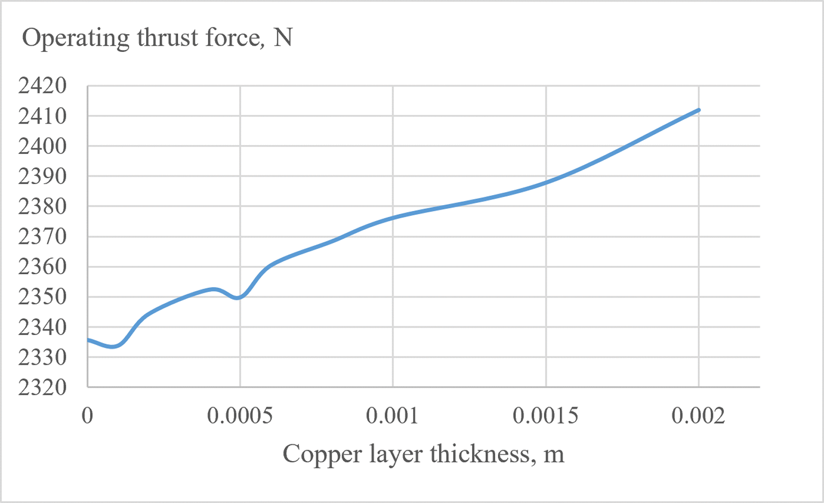
Figure 4. Dependence of operating thrust force (FTop) on copper layer thickness ∆Cu.
The figure shows the dependence of the operating thrust force on the copper layer thickness. The figure illustrates how the operating thrust force varies with increasing copper layer thickness. The values of graph were demonstrated in
Table 4. and the copper layer thickness varies from 0.0001 m to 0.002 m using the same discrete thickness values as those considered in
Figure 2 and
Figure 3.
The observed improvement in the LIM parameters is presumably primarily attributed to the reduction in the active resistance of the secondary element, which in turn reduces slip and improves traction, efficiency and speed of vehicle. Reduction of the active resistance of the secondary element was described in.35 The copper layer increases the electrical conductivity of the secondary element, thereby improving electromagnetic coupling between the secondary element and the stator, which contributes to an increase in the power factor. Additionally, the observed improvement in efficiency may be attributed to reduced losses in the secondary element. However, given the calculation data, it is necessary to determine the optimal copper layer thickness, thermal and mechanical effects, as well as edge effects. The validation of results is planned for subsequent studies using experimental setups and FEM analysis.
Based on the obtained calculation results, it can be concluded that a copper-coated secondary element can be effectively applied in LIMs intended for transportation systems requiring high thrust force and speed to facilitate the acceleration of the train. Such operating conditions are typical during start-up of heavily loaded train units or when operating on track sections with steep track gradients, where increased traction force and speed is required. These conditions are particularly relevant in regions with complex terrain, such as Armenia, where mountainous landscapes and variable elevation profiles impose additional traction demands on rolling stock. In such cases, the use of copper coated secondary elements may be considered for specific track sections, although the practical implementation of such solutions requires further technical and economic evaluation. The observed increase in thrust force can also be advantageous in conveyor and elevator drive systems, particularly under conditions involving short-term overloads. In such applications, copper-coated secondary elements may be used to enhance performance during peak load periods, with conventional designs applied under normal operating conditions. Such operational scenarios are common in industrial sectors including mining, metallurgy, construction materials production and logistics, where variable loads and transient operating regimes frequently occur.
Linear induction motors can be considered to replace permanent-magnet-based drives in applications where high thrust at low speeds and robustness are more critical than maximum efficiency, such as heavy transport systems, conveyors, and harsh-environment operations. The obtained results demonstrate that the use of copper-coated secondary elements indicates potential performance improvements while maintaining a fully rare-earth-free design. Rare-earth elements are also associated with supply-chain risks and environmental concerns, which motivate the development of alternative motor technologies. From a resource-efficiency perspective, the use of copper may also be advantageous in regions with abundant reserves, such as Armenia, which possesses significant copper resources. The utilization of locally available raw materials can reduce dependence on external supply chains and support the development of energy-efficient electromechanical systems aligned with national sustainability and industrial resilience goals.
5. Conclusion
The analysis presented in this study demonstrates that the use of copper-coated solid secondary elements is a promising approach to improving the performance of LIMs. The application of such coatings enables an increase in thrust force and favorable changes in electromagnetic characteristics, without requiring significant structural modifications of the secondary element. This study highlights the potential of LIMs as a rare-earth-free alternative to permanent-magnet-based drive systems in transportation and industrial applications. The increasing of the copper layer thickness shows the positive impact on LIMs electromagnetic parameters. However, the optimization of the copper layer thickness remains a critical factor, requiring further investigation. Additional studies should focus on the thermal and mechanical effects associated with the coating, as well as on the long-term reliability and practical implementation of this approach. The validation of results is planned for subsequent studies using experimental setups and FEM analysis.
Ethics and consent
Ethical approval and consent were not required.
Data availability
The data and calculation materials supporting the findings of this study are openly available in:
Acknowledgements
We would like to thank Mattia De Rosa (PhD Mechanical Engineering. Associate professor in Energy and Thermal Engineering at the University of Genoa, EU Horizon Europe STREACS project supervisor.) for his support within the structural advisory and writing this paper.
References
- 1.
Solomin VA, Zamshina LL, Solomin AV:
Linear asynchronous traction motors for high-speed rolling stock and their mathematical modeling.
Moscow:
FGBOU UMC ZHDT;
2015; 164. (In Russian).
Reference source
- 2.
Gieras JF:
Linear induction drives.
Oxford, UK:
Oxford University Press;
1994; 292.
Reference source
- 3.
Vintizenko I:
Linear induction accelerators for high power microwave devices.
Boca Raton, FL, USA:
CRC Press;
1st ed2018; 436.
Publisher Full Text
- 4.
European Commission:
Critical raw materials.
European Commission.
2026.
Reference source
- 5.
Veselovskiy ON, Konyayev AY, Sarapulov FN:
Linear asynchronous motors.
Moscow, Energoatomizdat;
1991; 256. (In Russian).
Reference source
- 6.
Ryabtsev I, Fomichov S, Kuznetsov V, et al.:
Surfacing and additive technologies in welded fabrication.
Springer;
2023; 226. Publisher Full Text
- 7.
Postnikov IM:
Designing of electrical machines. Gos. publishing house in technical letter.
USSR Kyiv.
1960; 909. (In Russian).
Reference source
- 8.
Boldea I:
Linear electric machines, drives, and Maglevs handbook.
CRC Press;
Second ed2023; 718.
Reference source
- 9.
Kaye RJ, Masada E:
Comparison of linear synchronous and induction motors.
Urban Maglev technology development program Colorado Maglev project Project Report.
2004; 22.
Reference source
- 10.
Antonov YF, Zaitsev AA:
Magnetic levitation transport technology.
Gapanovich VA, editors.
Moscow, FIZMATLIT:
2014; 476. 978–5–9221-1540-7. (In Russian).
Reference source
- 11.
Stumberger G, Zarko D, Aydemir MT, et al.:
Design and comparison of linear synchronous motor and linear induction motor for electromagnetic aircraft launch system.
Proceedings of the IEEE International Electric Machines and Drives Conference.
USA, Madison, WI:
1–4 June 2003; 1: 494–500.
Reference source
- 12.
Zhou B, Li Z, Zhao Y, et al.:
Rare earth elements supply vs. clean energy technologies: new problems to be solve.
Gospodarka Surowcami Mineralnymi - Mineral Resour. Manag.
2016; 32: 29–44.
Publisher Full Text
- 13.
Binnemans K, Jones PT, Blanpain B, et al.:
Recycling of rare earths: a critical review.
J. Clean. Prod.
2013; 51: 1–22.
Publisher Full Text
- 14.
Ya.M. K:
Method of manufacturing a magnetic circuit.
All-Union Scientific Research, Planning-Design and Technological Institute of Electrical Machine Building.
Author's Certificate: SU 1480021 A1, published 15.05.1989. Application №4145185 filed 10.11.1986. (In Russian).
Reference source
- 15.
Shumov YN:
High-speed and ultra-high-speed asynchronous machines abroad: a review of publications.
Elektrichestvo.
2011; 5: 36–41. (In Russian).
Reference source
- 16.
Wang S, Miao D-M, Shen J-X:
Optimal design of a linear induction motor for woodworking machine application.
17th International Conference on Electrical Machines and Systems (ICEMS).
Hangzhou, China:
2014; 3633–3637. Reference source
- 17.
De Oliveira RAH, Berger D, Schultz L, et al.:
Finite element analysis of the forces developed on linear induction motors.
In Proceedings of the 2015 IEEE 13th Brazilian Power Electronics Conference and 1st Southern Power Electronics Conference (COBEP/SPEC).
Fortaleza, Brazil;
29 November-2 December 2015; 1–6.
Reference source
- 18.
Sarapulov FN, Smolianov IA, Rodionov IE:
Investigation of the traction linear induction motor for conveyor train.
Russian Internet Journal of Electrical Engineering.
2018; 5(1): 34–37. (In Russian). Publisher Full Text
- 19.
Sarapulov FN, Smolyanov IA, Tarasov FE:
Study of the linear induction motor with bimetallic secondary element.
Acta Technica CSAV.
2018; 63(2): 205–220.
Reference source
- 20.
Mahto MK, Kumar A, Raja AR, et al.:
Cladding of copper sheet on mild steel using friction stir welding.
Int. J. Adv. Manuf. Technol.
2021; 118(9–10): 3345–3360.
Publisher Full Text
- 21.
Schlesinger M, Paunovic M:
Modern electroplating.
John Wiley & Sons;
5th ed2010; 752.
Reference source
- 22.
Privalov AS:
Features of cold gas-dynamic spraying as a technology for preserving the original properties of deposited materials.
In collection of scientific articles of the VIII International Youth Scientific Conference “Youth and Knowledge - a Guarantee of Success”.
Gorokhov AA, Kursk, editors.
2021; 3: 323–328. (In Russian).
Reference source
- 23.
Arkhipov VE, Londarskiy AF, Moskvitin GV:
Gas dynamic spraying: Structure and properties of coatings.
Moscow:
Krasand Publ;
2017; 239. (In Russian).
Reference source
- 24.
Arkhipov VE, Londarskiy AF, Moskvitin GV, et al.:
Application of copper coatings on steel by gas-dynamic spraying.
Metalloobrabotka.
2012; 2(68): 13–17. (In Russian).
Reference source
- 25.
Kozlov IA, Leshchev KA, Nikiforov AA, et al.:
Cold spray coatings (review).
Trudy VIAM.
2020; 8(90): 77–93. (In Russian). Publisher Full Text
- 26.
Assadi H, Gärtner F, Stoltenhoff T, et al.:
Bonding mechanism in cold gas spraying.
Acta Mater.
2003; 51(15): 4379–4394.
Publisher Full Text
- 27.
Schmidt T, Gaertner F, Kreye H:
New Developments in cold spray based on higher gas and particle temperatures.
J. Therm. Spray Technol.
2006; 15(4): 488–494. Publisher Full Text
- 28.
Champagne VK:
The cold spray materials deposition process.
Woodhead Publishing;
2007; 362p. Publisher Full Text
- 29.
Grujicic M, Zhao CL, DeRosset WS, et al.:
Adiabatic shear instability based mechanism for particles/substrate bonding in cold-spray process.
Mater. Des.
2004,
December 2004; 25(8): 681–688.
Publisher Full Text
- 30.
Stoltenhoff T, Borchers C, Gaertner F, et al.:
Microstructures and key properties of cold-sprayed and thermally sprayed copper coatings.
Surf. Coat. Technol.
2006; 200: 4947–4960.
Publisher Full Text
- 31.
Yin S, Suo X, Guo Z, et al.:
Deposition features of cold sprayed copper particles on preheated substrate.
Surf. Coat. Technol.
2015; 268: 252–256. Publisher Full Text
- 32.
Villafuerte J:
Modern cold spray: materials, process, and applications.
Cham, Switzerland:
Springer International Publishing;
2015; 429. Publisher Full Text
- 33.
Xiao M, Qiang X, Jiang F:
Effect of copper addition on the phase composition and microstructure evolution of Fe-based amorphous alloy coatings prepared by laser cladding.
Adv. Mater. Sci. Eng.
2022; 2022: 1–7. Article ID 3511432. Publisher Full Text
- 34.
Gnedenkov AS, Nomerovskii AD, Tsvetnikov AK, et al.:
Formation of the composite polymercontaining coatings on St3 steel using cold gas dynamic spraying technology.
Vestnik of the FEB RAS.
2022; 6: 35–45. (In Russian).
Reference source
- 35.
Mayilyan AL, Saghatelyan MA, Khangeldyan AG:
Calculating the parameters of a linear asynchronous machine with a secondary element covered with a copper layer.
Proceedings National Polytechnic University of Armenia: Electrical engineering, Energetics, Yerevan.
2023; 1: 68–79. (In Russian).
Reference source
- 36.
Kutsevalov VM:
Asynchronous and synchronous machines with massive rotors.
Moscow, Energiya:
1979; 160. (In Russian).
Reference source
- 37.
Mayilyan AL, Saghatelyan MA, Khangeldyan AG:
Improving the parameters of a linear induction motor with a massive secondary element.
Proceedings National Polytechnic University of Armenia: Electrical engineering, Energetics, Yerevan.
2024; 1: 19–30. (In Russian).
Reference source
- 38.
Khangeldyan A:
Calculation methodology of the double-sided linear induction motor. [Dataset].
Zenodo.
2026.
Publisher Full Text
- 39.
Kopylov IP, Klokov BK, Morozkin VP, et al.:
Designing of electrical machines: textbook.
Moscow, Yurait:
4th ed.2011; 767. (In Russian).
Reference source
- 40.
Epifanov AP, Kril DB:
Linear asynchronous electric drive of the monorail transport system for feeding in livestock farms.
Izvestiya of the Saint-Petersburg State Agrarian University.
2022; 66(1): 113–124. (In Russian).
Reference source
- 41.
Zhang Q, Liu H, Song T, et al.:
A novel, improved equivalent circuit model for double-sided linear induction motor.
Electronics.
2021; 10: 1644. Publisher Full Text
- 42.
Khangeldyan A:
Parameter calculations for the double-sided linear induction motor. [Dataset].
Zenodo.
2026.
Publisher Full Text
- 43.
Demirchyan KS, Neiman LR, Korovkin NV, et al.:
Theoretical foundations of electrical engineering.
Textbook for universities.
Saint Petersburg:
4th ed.2003; 3: 377. Electromagnetic field theory.
Reference source (In Russian)