Plain language summary
In this article, we present a low-cost, open-source, 3D printed centrifuge (mobilefuge) that is portable, robust, stable, safe, easy to build and operate. The mobilefuge doesn't require soldering or programming skills and can be built without any specialised equipment yet is practical enough for high throughput use. More importantly, the mobilefuge can be powered from widely available 5V USB ports, similar to those found in mobile phones and associated power supplies. This allows the mobilefuge to be used even in off-grid and resource limited settings. Performance of the mobilefuge is demonstrated by separating silica particles are from a suspension consisting of water and “glassmilk”. This separation process is one of the crucial steps in nucleic-acid amplification assays for reliable, low-cost diagnostic applications such as SARS-CoV2. We believe that beyond the nucleic-acid assays, the mobilefuge can have several applications as a microcentrifuge in the field of biomedical research and diagnostics.
Introduction
A centrifuge is one of the most commonly used general-purpose pieces of equipment in laboratories for various tasks such as to pellet cells1, precipitate DNA2, purify virus particles3 etc4. In most laboratories, various types of centrifuges are used depending on the applications. For example, low-speed, microcentrifuges are used to pellet cells, purification of DNA, etc while high-speed centrifuges can be used to determine sedimentation velocity etc.
Of all the applications, a centrifuge’s role in diagnostics is one of the most critical as it allows purification and separation of crucial analytes from the rest of the sample matrix5. However, many of these diagnostic applications require only a low-speed centrifuge. For example, applications such as separation of plasma from the blood samples6,7, purification of viral RNA from saliva samples only require a low-speed centrifuge8. Even such a low-speed centrifuge is not affordable in resource limited regions and point-of-care applications5.
Since a centrifuge is a simple and intuitive scientific device involving a single rotary mechanism, scientists and hobbyists exploited a variety of existing rotary mechanisms in consumer devices and toys to build low-cost centrifuges. These highly creative designs involve either a human powered rotary mechanism in a bike wheel8, a hand-crank torch light9, fidget spinners10,11, toys12–14 salad spinners15, egg beaters16 or electric motor powered rotary mechanism in consumer electronic devices such as drone motors17–23, computer fans24, hard disks25,26, DVD drives27 and rotary die grinder tools28.
During the Coronavirus disease 2019 (COVID-19) pandemic, the sudden demand and disruption of supply chains catalysed efforts to design and fabricate several different pieces of emergency medical equipment such as ventilators, thermometers, oxygen generators, personal protection equipment (PPE) at low-cost using locally available resources29. In this backdrop, a low-cost, affordable centrifuge gained a renewed interest, particularly to separate viral RNA in saliva for improving the sensitivity of low-cost nucleic-acid assays.
Particularly, the loop-mediated isothermal amplification (LAMP) assay is a simple nucleic-acid based diagnostic protocol that can detect small viral loads even in complex sample matrices such as saliva30. In addition, LAMP assay has high potential to be scaled up for point-of-care, near-patient-care and point-of-entry applications as it is highly reliable, sensitive, fast, cost-effective and doesn't require complex equipment31–34. Due to these benefits, a number of LAMP assays have been fast tracked by the United States Food and Drug Administration (FDA) for at-home tests for COVID-1935–38 and have the potential to bring down the cost of each test to less than a dollar9,30,39,40.
In particular, a LAMP assay that was developed at Harvard University can detect single virtual RNA per microliter from saliva samples30. This is significant as it eliminates elaborate sample collection methods through nasal swabs, thereby decreasing the associated sample collection risks while further reducing the costs and resources required. However, this Harvard assay and similar low-cost LAMP9 assays require a centrifuge to separate viral RNA in saliva from other inhibitors.
Without the centrifugation step, LAMP assays are less sensitive40,41 down to 50 viral particles per microliter from one viral particle per microliter30. As a result, LAMP assays would be limited only to identify individuals with moderate or high viral load and would not be suitable to detect viral infections in individuals with low viral load such as individuals with onset of infection or recovering from the infection.
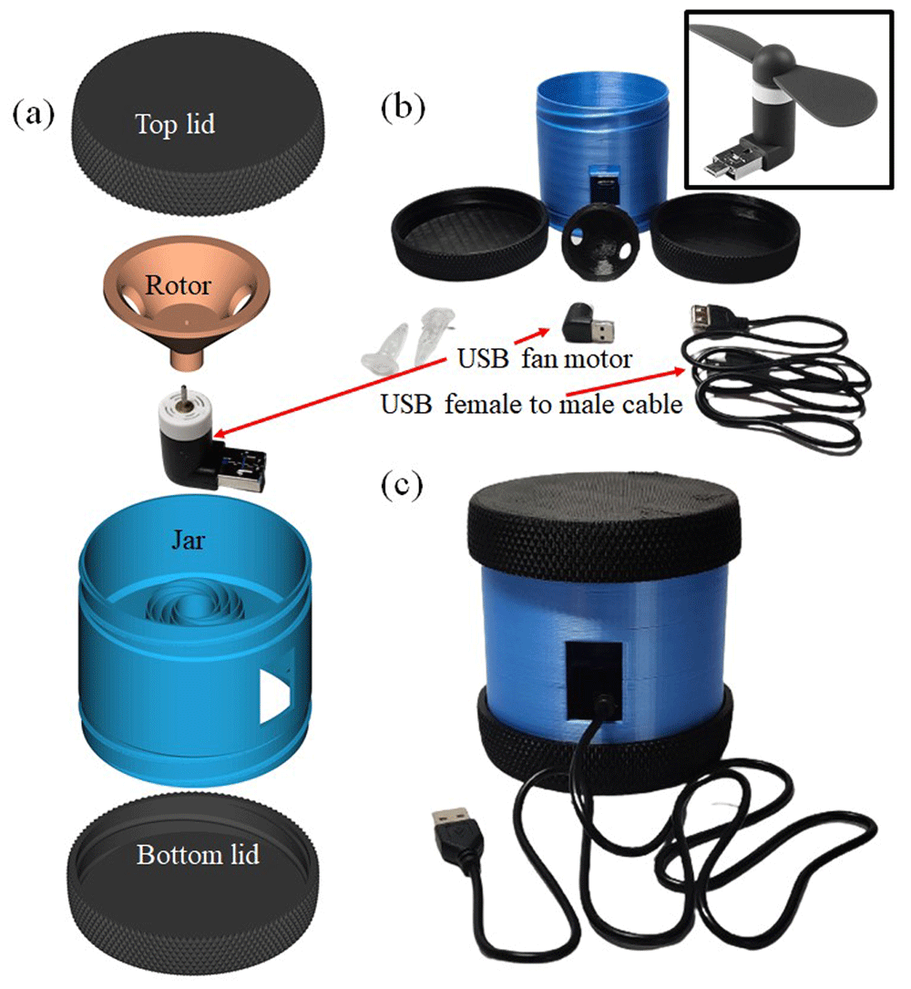
Figure 1.
(a) Computer aided design diagrams of 3D printed parts required for the mobilefuge. (b) The 3D printed parts and the electrical parts required to fabricate the mobilefuge. The Universal Serial Bus (USB) fan that powers the mobilefuge is shown in the inset. (c) Completely assembled mobilefuge.
Furthermore, another low-cost assay that combines Recombinase Polymerase Amplification and LAMP was proposed to achieve high sensitivity and selectivity42. Without a centrifuge such LAMP assays require 65% more reagents which would lead to an increase of cost per test. Therefore, a centrifuge is a crucial piece of equipment for LAMP assays for separating the viral RNA in saliva from other inhibitors to increase the wide adoption of LAMP assays to achieve affordable SARS-CoV2 testing.
In this context, Prakash’s lab from Stanford University demonstrated a low-cost centrifuge that was realised by cleverly exploiting a hand-crank rotation mechanism in LED torch lamp9 for a low-cost LAMP assay. A hard drive motor-based centrifuge was developed as part of another low-cost LAMP assay equipment26. It can be argued that many of the earlier mentioned centrifuge designs with several rotational mechanisms can be adopted for the purpose of LAMP protocols. However, human powered centrifuges might not be practical for high throughput use in medical labs. They can cause repetitive strain injury and offer limited safety while in operation43. On the other hand, most of the centrifuge designs that involve electric motors require high power and complex fabrication techniques. This is understandable as they were designed for general lab purposes which require high speed with speed control options, thus requiring many components and complex build procedures.
The problem of sample preparation for LAMP-based diagnostic assays is a different challenge that requires a simple centrifuge design that does not need to have high rotational speed yet must be practical enough to be deployed for diagnostic purposes. To address this challenge, we designed a 3D-printed centrifuge henceforth referred to as the mobilefuge. The mobilefuge consists of a Universal Serial Bus (USB) fan motor that can be powered by a USB power source. In Figure. 1. (a) we show the blow-up picture of the mobilefuge, in Figure.1 (b) components used to build the mobilefuge and in Figure. 1(c), a fully constructed mobilefuge.
The main objective of the mobilefuge is to build a stable, scalable, portable, affordable, robust, and easy to build centrifuge that can be powered using widely available 5V USB outlets, including smartphones. In the following sections, we will describe the fabrication of the mobilefuge and evaluate its performance to generate the rotational speeds required for LAMP assays. Finally, we discuss the benefits of mobilefuge such as portability, safety, and scalability in comparison with existing centrifuge designs.
Methods
Design files
The enclosure for the mobilefuge consists of three parts: jar, top lid, and bottom lid. As shown in Figure. 2(a) and (b), the main jar has a spiral placeholder (adopted from Reference. 44) to hold the USB fan motor in place and helps in stabilising the motor vibrations20. The top and bottom lids are locked to the main jar through the threads (see Figure. 3(a)) which makes the mobilefuge assembly easy. This enclosure design is adopted from the jar and lid design in Reference. 45. The top lid provides safety by protecting in case centrifuge tubes or its contents escaping from the rotor while the bottom lid provides room for the USB plug. The rotor of the mobilefuge shown in Figure. 3 (b) is adopted from an earlier centrifuge design in Reference. 46 to press-fit to the USB motor axis and hold two centrifuge tubes.
All the above-mentioned computer aided design (CAD) parts are designed using open-source parametric CAD software OpenSCAD (RRID:SCR_018870)47. These 3D-designs are then exported as stereolithography (STL) files. These STL files are further translated into a list of instructions to the 3D-printer, i.e., G Code by using a Ultimaker Cura software (RRID:SCR_018898) which slices the 3D model into 2D layers. The CAD and the STL files of the mobilefuge are available at Reference. 48 and at NIH 3D exchange.
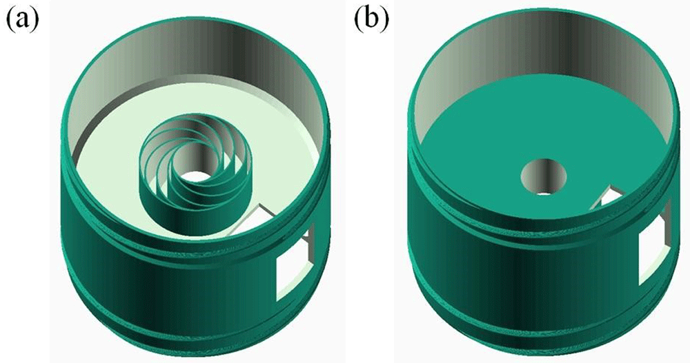
Figure 2.
(a) Top view of the jar design file of the enclosure of the mobilefuge designed in OpenScad. (b) bottom view of the jar design file of the enclosure of the mobilefuge designed in OpenScad.
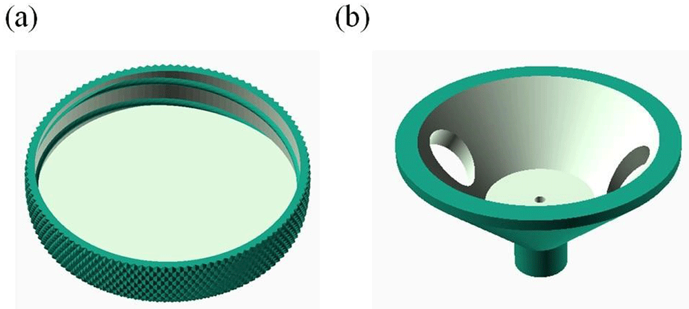
Figure 3.
(a) Lid of the mobilefuge’s enclosure designed in OpenScad and (b) Rotor of the mobilefuge designed in OpenScad.
Bill of materials
In Table 1, the three 3D-printed parts: jar, lids and rotor are 3D-printed in house on a Monoprice select Mini V2 3D-printer49 using PLA material with following settings: 10% infill and support structure. Support structures are removed after the objects are 3D printed. The cost of these 3D-printed parts is estimated assuming a $22.99 per kg spool of PLA material50.
Table 1. Bill of materials to construct the mobilefuge device.
| Designator | Component | Number | Cost per unit
-currency | Total cost
- currency | Source of
materials | Material
type |
|---|
| Lid | Lid for enclosure | 2 | USD 0.94 | USD 1.88 | In house | PLA |
| Jar | Main part of enclosure | 1 | USD 2.78 | USD 2.78 | In house | PLA |
| Rotor | Centrifuge rotor | 1 | USD 0.24 | USD 0.24 | In house | PLA |
| Motor | USB fan motor | 1 | USD 1 | USD 1 | Aliexpress | NA |
| Power cable | USB OTG | 1 | USD 1 | USD 1 | Aliexpress | NA |
| Pad* | Self-adhesive damping pad | 1 | USD 1 | USD 1 | Aliexpress | NA |
| Total | | | | USD 7.9 | | |
The USB fan motor is used to power the mobilefuge (See inset in Figure. 1(b)). These USB fans contain a USB/microUSB male connector and can be plugged directly into USB/microUSB ports on laptops, smartphones, and power banks. The USB fans have speeds in the order of 7500 rotations per minute (RPM) to circulate the air, therefore highly suitable for the centrifuge applications that only require low RPMs. A USB female to male cable is used to connect the USB fan motor to a USB power source as shown in Figure. 1(b) and (c). Instead of this female to male USB connector, a USB On-The-Go (OTG) cable can be used to power the motor from a smartphone’s charging port. Each of these electrical parts used in the mobilefuge can be bought online as well as in local electrical stores as these are sold as accessories to smartphones.
Build instructions
Assembling of the mobilefuge is quite simple and should take less than a minute as shown in the Video V151 as well as described in the following:
i. Press-fit the USB fan motor is at the bottom of the jar as shown in Figure 4. (a).
ii. Connect the female side of USB cable to the male side of the motor as shown in Figure 4. (b).
iii. Fix the bottom lid part to the jar part of the enclosure as shown in Figure 5. (a) and Figure 5. (b).
iv. Press-fit the rotor to the shaft of the USB fan motor as shown in Figure 6. (a).
v. Fix the Top lid to the main jar of the enclosure as shown in Figure 6. (b) to complete the assembly of the mobilefuge.
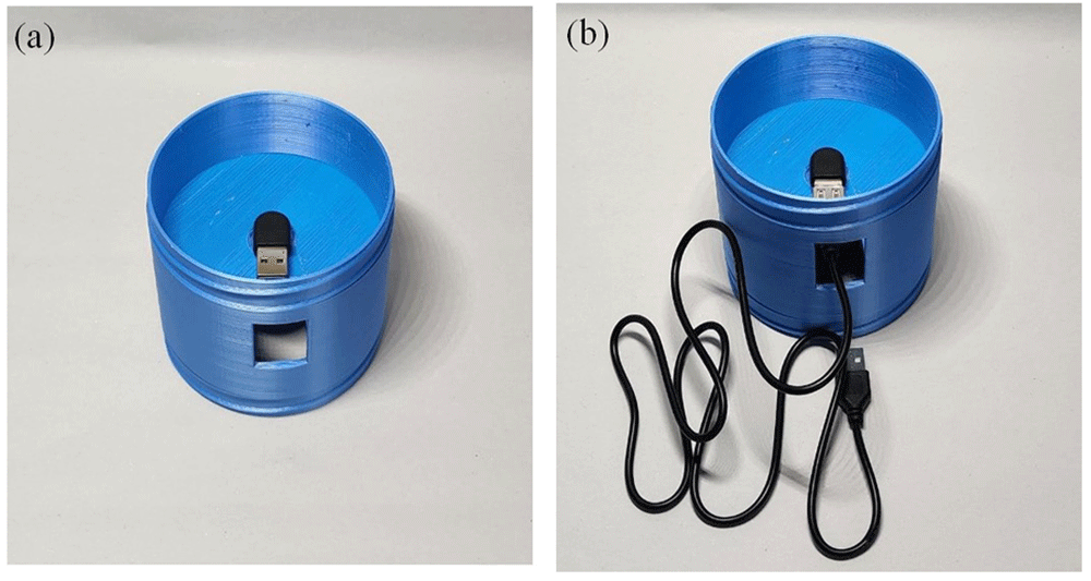
Figure 4.
(a) Fan motor is press-fitted at the bottom of the jar enclosure. (b) USB cable is connected to the motor.
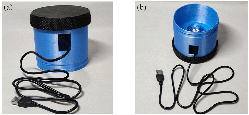
Figure 5.
(a) Bottom lid is fixed to the jar part of the enclosure. (b) Same as (c) but showing the top view of the jar with the bottom lid in place.
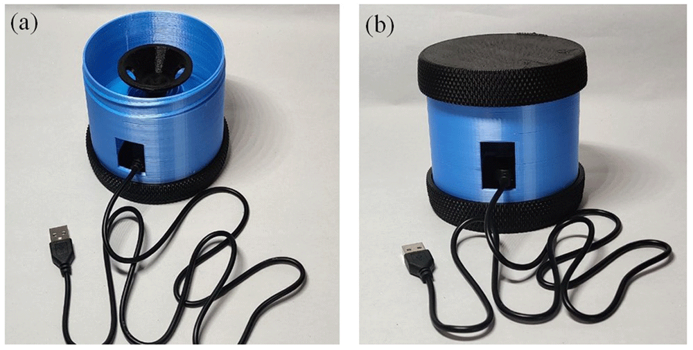
Figure 6.
(a) Rotor is press-fitted to the fan motor. (b) Top lid is threaded to the main jar of the enclosure to complete the assembly of the mobilefuge.
Operational instructions
Operation of the mobilefuge is fairly straightforward and is shown visually in the Video V151 as well as described in the following for completeness
i. Open the top lid of the mobilefuge by unscrewing it from the jar enclosure.
ii. Insert two 2 mL centrifuge tubes each with the same volume of suspension liquid in the rotor as shown in Figure. 7 (a)
iii. Close the top lid by screwing it to the jar enclosure as shown in Figure. 7 (b).
iv. Connect the USB cable of the mobilefuge to any 5V providing USB power source to start the centrifugation with the mobilefuge.
v. To stop the mobilefuge after the intended time of use, just disconnect the USB cable from the power source.
vi. Once the mobilefuge is stopped, open the top lid to remove the centrifuge tubes from the rotor.
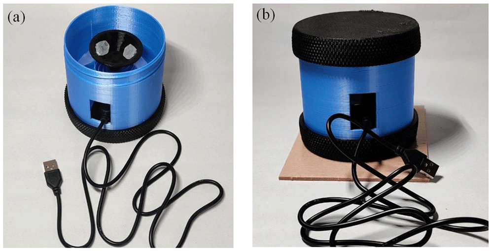
Figure 7.
(a) Insert the centrifuge tubes in the rotor. (b) Close the enclosure with the lid and place the mobilefuge on a self-adhesive damping pad to improve the stability.
Validation and characterization
Calculation centrifugal force. The performance of a centrifuge is measured in the units of relative centrifugal field (RCF). The RCF describes and compares the strength of the acceleration applied by the centrifuge on a sample relative to the earth’s gravitational force.
Centrifugal field on a particle with a mass m is given by Fc = mω2R52,53 where R is the distance between the centrifuge tube and the centre of the rotor (See Figure. 8 (a)) and ω is the rotational speed of the centrifuge52,53. The earth’s gravitational force on the same particle is Fg = mg where g is the earth’s gravitational constant.
The RCF can be expressed mathematically as52,53:
By substituting, g = 9.8 ms–2 (s represents seconds) and , into Equation 1 yields:
From Equation 2, RCF can be measured given the rotational speed (RPM) and the distance (R) from the centre of the rotor to the centrifuge tube values of a centrifuge in millimetres. We measured the rotational speed of the mobilefuge using a non-contact tachometer (AT6, Tenmacorp) and R values using a digital vernier calliper device (Mitutoyo, Catalogue no: 500-151-30).
We found that the USB-fan motor spins at the speed of ~7500 RPM using the tachometer. Therefore, the corresponding maximum RCF of the mobilefuge can be estimated from Equation (2) is 2835 for Rmax = 45 mm (see Figure 8(a)). However, when the mobilefuge is loaded with the 2ml centrifuge tubes, the rotor speed is decreased to 3600 RPM. Therefore, the maximum RCF of the mobilefuge is 650. Note that the rotational speeds above 2000 and the corresponding RCFs above 600 are sufficient to perform the LAMP assay for detection of SARS-Cov2 as described in References. 9,30.
Measuring the power consumption of the mobilefuge. We measured the power consumption of the mobilefuge by using a USB-A power meter (PAC1934 from Microchip Technology Incorporated), by connecting the power meter between the USB-source and the mobilefuge. We found that the mobilefuge consumes only 314 mA of current at 5V (see Reference. 54), which is less than the 500 mA of current that can be provided by the USB ports for connecting peripherals.
Preparation of “glass milk” solution. To demonstrate that the mobilefuge can be useful for the purification process during the LAMP assays, we separate the silica particles from a suspension consisting of water and “glassmilk” using the mobilefuge. This centrifugation process mimics the sample purification step in the LAMP assay protocols where viral RNA separated from the saliva.
The “glass milk” suspension along with chaotropic salts acts as a binding mix in the low-cost LAMP assays to capture the viral RNA from the cleared saliva solution containing the viral particles9,30. This “glass milk” solution suspension was the predecessor to the commercial silica-based column nucleic-acid purification kits30,55.
The “glass milk” solution is usually prepared by mixing equal amounts of distilled water and silica particles after removing the fine silica particles56,57. The “glass milk” suspension was prepared by adding 5 grams of 325 mesh silicon dioxide (sigma 342890) to a 50 ml tube consisting of 50 ml of water. The suspension was left untouched until the silica particles were precipitated at the bottom of the tube and then the supernatant was poured off to remove the fine silica particles smaller than 1 micron from the solution. Then another 50 ml of water is added to the tube with the precipitated silica particles to make the “glass milk” suspension.
Results
Evaluating performance of the mobilefuge
As explained in the earlier section, we will demonstrate the centrifugation ability of the Mobilefuge by separating the silica particles from a suspension consisting of water and “glass milk”. This centrifugation process mimics the sample purification step in the LAMP assay protocols where viral RNA separated from the cleared saliva solution. For this purpose, 5 μL of the “glass milk” is added to 500 μL of distilled water in a 2mL centrifuge tube to mimic the cleared saliva solution. This 2 mL centrifuge tube is placed in the mobilefuge, along with a dummy 2 mL tube with equal amounts of water and spun for 30 seconds. We show the image of the centrifuge tube with “glass milk” solution before and after the centrifugation in Figure. 8(b) and 8(c) respectively. It is visible from these images that silica particles are trapped at the end of the centrifuge tube as a pellet while leaving the water as a supernatant. In LAMP assays, RNA of the SARS-CoV2 virus particles present in the saliva will bind to the silica particles and become a pellet at the end of the centrifuge tube. After pouring off the supernatant, this pellet containing the viral nucleic acids is retained for further processes in a LAMP assay. Note that LAMP assay for detection of SARS-CoV2 is not carried out in this article.
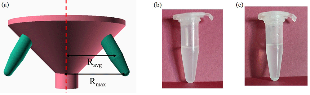
Figure 8.
(a) Schematics to show the distance “R” between the rotor and a centrifuge tube used in Equation (2). (b) “glass milk” solution with silica particles in a 2mL centrifuge before the centrifugation (c) Pellet of silica particles formed after centrifugation of the “glass milk” solution with the mobilefuge for 30 seconds.
Evaluating stability of the mobilefuge
Equipment such as a centrifuge that consists of rotating parts is prone to vibrations due to unbalanced rotors which will lead to instability. In the case of the mobilefuge, since the rotor is 3D-printed, it is sometimes difficult to mount it exactly at the centre of the motor. Similarly, any small difference in the weights of the centrifuge tubes will also lead to an unbalanced rotor and consequently will result in vibrations. It is highly desirable to have a stable operation of centrifuge for long term durability and safety purposes.
Therefore, we measured the stability of the mobilefuge by indirectly measuring the vibrations on a surface where the mobilefuge is placed. In particular, we measured the vibrations caused by the mobilefuge loaded with two 2 mL centrifuge tubes each with 1 mL of water on a table. For this purpose, we recorded data from inbuilt accelerometers in a smartphone58 (Samsung Galaxy note 10) placed on the same table surface using the Phyphox smartphone application59. Phyphox is an open-source smartphone application built to perform experiments using inbuilt sensors in smartphones. Along with this accelerometer data, the noise generated while the mobilefuge is in operation is also recorded with the microphone in the same smartphone and Phyphox smartphone application.
In Figure. 9, we show the accelerometer sensor data58 (sampled every 20 ms) from the smartphone plotted against the time. Figure 9. (a) and Figure. 9(b) represent the accelerometer data when the mobilefuge is not in use and in use, respectively. The red, green, and blue lines indicate the accelerometer data in x, y and z directions respectively. The corresponding standard deviations “σ” of this accelerometer data are indicated above these lines. It is evident from the accelerometer data and standard deviation values that mobilefuge causes considerable vibrations on the table surface when in use.
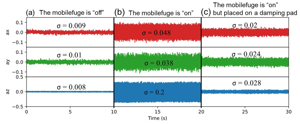
Figure 9. Time variation of accelerometer sensor data from a smartphone placed on the same surface next to the mobilefuge is plotted to show the vibrations caused by the mobilefuge58.
(a) The mobilefuge is “off” (b) The mobilefuge is “on” (c) The mobilefuge is placed on a damping pad to reduce the vibrations caused by the mobilefuge. The labels on the y-axis, ax, ay and az represent the accelerometer data in the x, y and z directions respectively. The standard deviation “σ” of the variation in accelerometer data is shown above for each data set.
To decrease these vibrations, we attached a commonly available self-adhesive damping pad at the bottom of the mobilefuge and showed the corresponding accelerometer data in Figure. 9 (c). It is clear that the damping pad improves the stability of the mobilefuge as expected as these pads are made for damping the vibrations of household electric utilities. We also noticed that with the use of the damping pad, the noise recorded in the microphone decreased by 13dB indicating the improved stable operation of the mobilefuge60.
Discussions
So far, we evaluated that the mobilefuge can generate enough force to separate the silica particles from “glass milk” solutions, which is a crucial process for purifying viral RNA from the saliva samples in LAMP assay protocols. In the following, we will explain why the mobilefuge can be a better solution compared to the existing centrifuge designs for this purpose.
Affordability
Except the 3D printed parts, the mobilefuge requires only two parts, i.e., a USB fan motor and a USB female to male cable. Each of these costs less than one dollar (at the time of writing) which makes the total cost of the mobilefuge extremely low. This is possible as the required speed of the centrifuge is low for the LAMP assay which can be achieved with such a small motor in USB fans. To the best of our knowledge only a few centrifuge designs, that are manually operated, such as paperfuge12, 3Dfuge13 and handyfuge9 can be lower cost than the mobilefuge. However, as explained earlier, manually operated centrifuge designs might not be suitable high throughput applications where many samples need to be processed.
Simplicity
The mobilefuge consists of a minimum number of parts required for a centrifuge without sacrificing safety features. Moreover, the mobilefuge exploits the ubiquitously available USB cables for connecting the motor to a power source. Therefore, unlike other electricity powered centrifuges17–27 the mobilefuge requires neither soldering of any electrical components nor programming of microcontrollers. Thus, building the mobilefuge device is a quick and relatively easy process even for non-experts (see Video V151). Also, there is no other equipment required other than the 3D printer to build the mobilefuge. This simple design and build process also allows fast servicing of the mobilefuge in the case of worn or repair of individual parts which is crucial for high throughput use cases.
Scalability
The mobilefuge can be built by anyone with a 3D-printer. During the COVID-19 pandemic, it has been witnessed that 3D printers are widely available to the public even in low income countries and they are willing to help to make medical equipment at home and donate to the community61–64. This is particularly important when supply chains are constrained, and demand is high for medical equipment. Therefore, if required in high volume, the mobilefuge devices can be built and distributed with the help of the 3D printing community. The low number of electric parts, their low-cost and ubiquitous availability helps to scale-up the production of the mobilefuge. Furthermore, the size of the entire mobilefuge is extremely compact when compared to many 3D printed centrifuge designs. Therefore, the mobilefuge’s small size allows it to be printed on even low-cost 3D printers with small print volumes such as Monoprice select Mini V2, while large 3D printers could print more than one mobilefuge in a single run.
Low-power consumption
One of the main features of the mobilefuge is that it can be powered from mobile phones and associated power supplies such as battery banks that can supply 5V. This is because the required rotational speed of the centrifuge is low for purification of viral RNA using silica suspensions, it consumes very little power. We found that the mobilefuge consumes only 314 mA of current54 which is less than the 500 mA of current that can be provided by the USB ports for connecting peripherals.
The market value of portable power banks and wall-plug chargers is around USD 9 billion and USD 20 billion48 respectively. This huge market and the use of 4.2 billion mobile phones in the world49 indicate the scale of availability of power sources that can run the mobilefuge. This makes the mobilefuge easy to deploy in remote and resource limited regions where the direct electric power supply might be scarce and unpredictable.
Safety
Safe operation of the equipment is crucial to convince the stakeholders to employ the mobilefuge for its intended use near the patients in resource limited settings. Centrifuges, particularly those that have high speed rotors are notoriously unsafe65. Also, centrifuge tubes can escape from the rotors and can cause serious injuries and leaked contents can cause biohazard. These risks are mitigated in the mobilefuge by choosing a low-speed motor that provides no more G-force than necessary. Additionally, screw type top lid helps to protect in case either centrifuge tubes or its contents escape from the rotor. Furthermore, use of less power hungry and consumer grade electrical components decreases the potential for electrical hazards.
Flexibility
All the 3D-printed parts of the mobilefuge are designed using an opensource CAD (OpenScad) software and the source files as well as STL of these parts are made freely available. Therefore, it is possible for others to optimise the design of the mobilefuge for further improvements such as to print the entire mobilefuge body i.e., bottom, central part and the top lid in one print or to increase the number of slots in the rotor to hold more tubes. Additionally, one can also use a USB fan speed controller (see Figure. 10) to adjust the speed of the mobilefuge if such features are required. The USB speed controller shown in Figure. 10 (a) allows the standard 5V output from USB ports to be stepped-up to 12V continuously, without requiring any soldering of parts. Such a step-up of the voltage helps to achieve higher RPMs which could be quite useful for applications like separation of plasma from blood to diagnose malaria13.
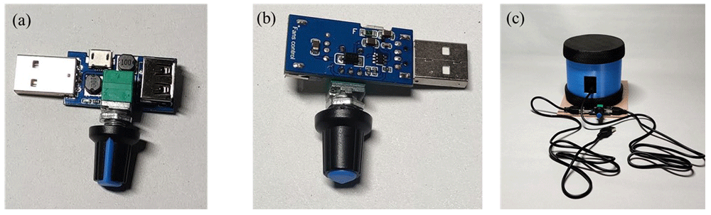
Figure 10.
(a) Front view of the Universal Serial Bus (USB_ fan speed controller (b) Back view of the USB speed controller (c) The mobilefuge with USB fan controller to control the speed of the mobilefuge.
Despite the several advantages discussed above, there are a few limitations with the mobilefuge:
Speed variation
Although widely available, the USB fan motor is not a standard part and thus the speed of the centrifuge might vary with the USB-fan motor acquired. However, for the nucleic-acid extraction assays which require only 3000 RPM, the variation in the motor speed is unlikely to be an issue.
3D-printer errors
Errors in 3D-printed parts are common. For example, warped 3D-prints of the rotor part might result in the improper installation of the rotor onto the shaft of the USB fan motor. These errors can lead to imbalance of the mobilefuge and cause large vibrations. The 3D-print errors can be minimised by 3D-printing the rotor part at higher resolution (i.e., smaller layer height) compared to other 3D-printed parts. In addition, cyanoacrylate glue (i.e., super glue) can be applied on the motor shaft for improving the adhesion of the rotor to the shaft of the motor.
Limited number of tubes
In the current design, the mobilefuge can only hold two 2 ml centrifuge tubes at once, which is adequate for intended application of mobilefuge. However, if the mobilefuge is constructed with either heavier tubes or with a higher number of tubes, it will result in the decrease in the RPM/RCF of the mobilefuge.
Conclusions
Overall, in this article a low-cost, open-source, 3D printed centrifuge is presented. The mobilefuge is demonstrated for separation of silica particles from the “glass milk” solution which is useful for purifying DNA or RNA. Beyond these nucleic acid purification applications, the mobilefuge can be employed where low RPM/RCF is sufficient and desired such as the separation of fibrin7, plasma6,10, red blood cells and bacteria from the blood66. Similarly, the mobilefuge with its low RPM/RCF is quite useful for the urine analysis67,68, sperm analysis69,70 and centrifugation-based point-of-care diagnostics71. The mobilefuge can also serve as a useful tool to be built by school children for their science labs and remote learning as it requires only a few non-3D printable parts and does not require soldering or programming skills which might not be suitable for school settings.
Ethics and consent
Ethical approval and consent were not required