Introduction
The envisaged European greenhouse gas (GHG) fleet emission limits for 2025 and 2030 require a massive market introduction of battery electric vehicles (BEVs). Air quality regulations, such as potential zero-emission zones in cities will further drive the demand for these vehicles. Nowadays, the underlying technology of BEVs is sufficiently matured to initiate this shift in mobility. Next to this, BEVs are approaching cost parity with vehicles driven by internal combustion engines (ICEs). However, range anxiety is still a major barrier towards a mass-market adoption of the BEV. The straightforward solution to overcome this barrier is to increase the driving range and to shorten the charging times, while at the same time the resource efficiency and environmental performance of the battery is improved. That’s where the LIBERTY project steps in. The overall project target is upgrading the lifecycle, BEV battery performance, safety and lifetime from a sustainability perspective. Accordingly, the key objectives of LIBERTY are:
• Objective 1: To achieve a range of 500 km on a fully charged battery pack;
• Objective 2: To achieve a short charging time below 18 minutes;
• Objective 3: To achieve an ultimately safe battery system;
• Objective 4: To achieve a long battery lifetimeallowing a (total) BEV mileage of 300.000km
• Objective 5: To achieve sustainability over the battery pack’s entire life cycle, reducing its environmental impact by 20 % compared to the benchmark.
All these project objectives are targeted by only contemplating developments aimed at the battery pack (not on the remaining elements of the powertrain and the vehicle). Thereby, LIBERTY brings in disruptive technical innovations to overcome such barriers while targeting a significant impact on the BEV performance metrics. Table 1 describes the main features targeted by the battery pack development in LIBERTY, compared to those of the benchmark vehicle considered in the project.
Table 1. Main features of the LIBERTY battery pack compared to the benchmark vehicle.
| Parameter | Benchmark:
EQC 2019 | Target:
LIBERTY EQC |
|---|
| Battery system capacity [kWh] | 80 | 96 |
| Battery system weight based on 80 kWh battery capacity [kg] | 650 | 520 |
| Max. charging power [kW] | 110 | 350 |
| Charging window 10-80% SoC [min] | 40 | < 18 |
| Range (WLTP) [km] | 417 | 500 |
| Battery life (no. of cycles to 80% DoD) | 500 | 1000 |
| Mileage [km] | 160,000 | > 300,000 |
Methodology
The LIBERTY project targets the development of a complete battery pack from the design requirements phase up to the system level validation, and ultimately its integration into a Mercedes EQC demonstration vehicle. Thereby, starting from current innovations at TRL (Technology Readiness Level) 4, the final result of LIBERTY will be a TRL 7 battery system (demonstrator in operational environment). The main stages followed by the methodology adopted in the project, which mimics the so-called V-shape design methodology, are:
1. Defining the specifications using interdisciplinary considerations and stakeholder knowledge regarding safety, first life (range, charging time, charging power, etc., see Table 1), second life, eco-design (through life-cycle assessment (LCA), recycling, TCO (total cost of ownership) targets and vehicle requirements.
2. Design of the battery system. Based on the specifications, a battery system will be designed including mechanical, thermal, electrical and BMS (battery management system) design. Factors taken into account are industrialisability, suitability for mass production (input from OEM and TIER1 suppliers) and safety. Based on the design, the requirements of all battery system components in terms of performance, weight, volume, and interfaces will be defined. The design will evolve based on the development of the components in the next step. This ensures that required adaptations to components from a battery system and requirements point of view are noticed and adaptations to the components can be made on time. Next to this, regular checks of the battery system design are performed to ensure successful integration in the Mercedes EQC.
3. Developing the battery system components using the requirements from the battery system design. Prototyping and functional testing of the components is part of the development. Regular checks of the designs of the components are performed to ensure successful integration in the battery system and the Mercedes EQC.
4. Developing test procedures for safety and performance testing from cell to battery system level. These test procedures will be validated in step 6.
5. Assembling the battery system and integration of the system in the Mercedes EQC. Adaptations to the components will be made when required.
6. Demonstrating the battery system performance (incl. range, fast-charging) and safety by using the developed test procedures.
7. Assessing the impact of LIBERTY by means of LCA and TCO using the outcomes from the previous steps, interdisciplinary considerations and stakeholder input.
Intermediate Results
The challenging objectives targeted in the LIBERTY project require breakthrough technologies and innovations which can bring the features of the battery pack to be developed beyond the state of the art. Therefore, LIBERTY’s objectives will be achieved by developing a new battery system through smart combinations and implementations of innovations as described in Figure 1.
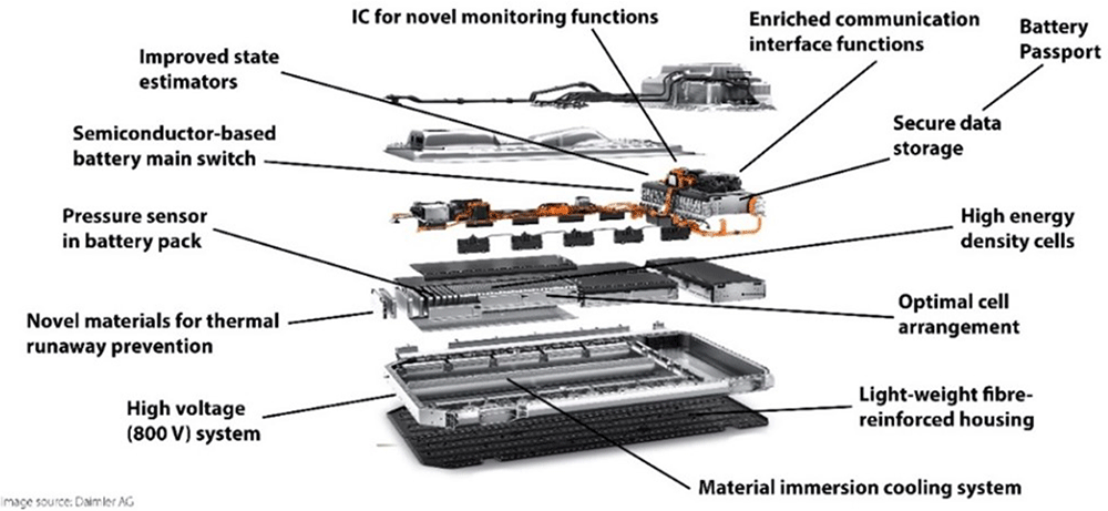
Figure 1. Main innovations addressed in LIBERTY superimposed on the battery pack of the benchmark vehicle.
The innovations within LIBERTY will lead to a compact high-performance battery pack with advanced diagnostic and control features and functionalities. In terms of consumer’s value, it brings extended range, short charging times, long travel distance capability, safety, reliability, user confidence and affordability.
In the following subsections some of the main innovations addressed in the project are briefly described.
Lightweight battery housing
To develop a lightweight battery housing with sufficient strength and rigidity, in order to meet operational load and crashworthiness requirements and tightness for the dielectric cooling fluid, the use of the so-called “organosheets” (thermoplastic pre-impregnated composites reinforced with glass or carbon fibres) will be investigated in LIBERTY. Organosheet materials show a good strength-to-density ratio compared to metals. Table 2 shows the comparison of different proposed organosheet materials compared to metals. For the housing materials, the tensile modulus should be at least 20 GPa, the strength 400 MPa and the density as low as possible.
Table 2. Comparison of different proposed organosheet materials compared to metals.
| Materials | Tensile modulus
[MPa]
(Dry/HR50) | Strength [MPa]
(Dry/HR50) | Density
[g/cm3] |
|---|
| Organosheet PA6 GF50 | 22,400 / 21,500 | 404 / 390 | 1.8 |
| Organosheet PA66 CF50 | 55,000 / 55,000 | 700 / 700 | 1.46 |
| PA6 GF30 (short fibres) | 11,700 / 6,500 | 140 / 80 | 1.36 |
| Steel | 210,000 | 175-1500 | 7.85 |
| Aluminium | 70,000 | 150-300 | 2.7 |
| Magnesium | 42,000 | 135-285 | 1.8 |
LIBERTY will investigate which organosheet materials can be used for the battery housing. However, the use of these fibres would also make the housing more expensive, so an optimum has to be found.
Cell-to-pack approach
In LIBERTY, the cells will be placed with optimal distance by using a spacer assembly which ensures that each battery cell remains at its predetermined location. A lightweight material will be chosen as a spacer material, which will also have a relatively low thermal conductivity coefficient to avoid any thermal energy exchange in case of a single-cell thermal runaway. The thickness of the spacer will be optimised with regards to high energy density of the battery pack and space design requirements, the required distance to avoid short circuit and the performance of the immersion cooling system. Optimal cell arrangement will decrease non-homogenous heat distribution and will require less cooling power. In addition, issues in terms of cell mounting, applying pressure to prevent (excessive) swelling, cell configuration and cell orientation will be addressed. All these aspects are still relevant topics of research towards approaching a cell-to-pack concept as targeted in LIBERTY.
Active safety system to prevent thermal runaway
Thermal runaway propagation could be avoided by having a system in place that has the capability to extract and dissipate a large amount of heat in a few seconds1. This will be realised in LIBERTY by the development of an innovative active safety system, see Figure 2. This system uses two kinds of materials: i) a so-called thermal fuse and ii) a fire-retardant material based on a super-insulating material with dielectric properties, which will be placed between the separated cells or cluster of cells. The thermal fuse material is a compartment with a fluid inside that contributes to avoiding thermal runaway propagation at the cell/module scales. Its role is to cut the transfer of heat analogous to conventional electric fuses. At normal battery operating temperature, the thermal fuse will be in a liquid state. In case of a cell heating up, this material will boil and evaporate and thereby extract heat from the cell/cluster. Additionally, the presence of a high-performance thermal insulating material will reduce and delay the thermal energy transfer to neighbouring cells, thus helping to limit the thermal runaway event.
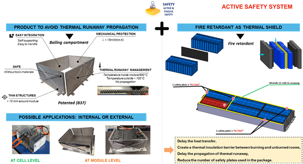
Figure 2. Active safety system principle.
Cooling system
In LIBERTY, a cooling solution using partial immersion with a sprayed dielectric fluid will be developed. A schematic overview of this system is shown on Figure 3. The principle of the use of this method is that the liquid is directly sprayed over the cells while only a small portion of the cells is immersed. The proposed solution will therefore be able to deal with the heat transfer peak required during fast-charging. The advantages of this system are:
• Enhancement of the cooling heat transfer coefficient compared to traditional cooling plates;
• The use of a small volume of fluid, which reduces the overall mass of the battery;
• A controllable spray leads to better temperature homogeneity of the cells;
• Hot points (bus bars, electric connections,..) are avoided;
• Reduce the risk of thermal event propagation.
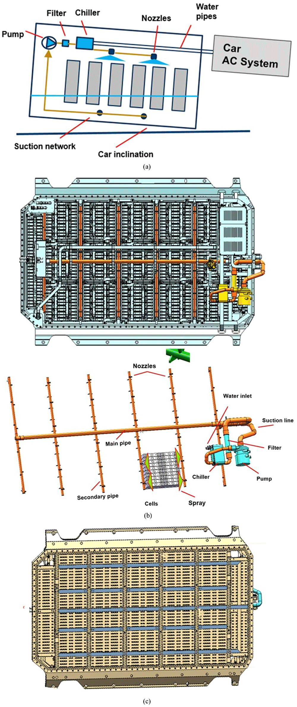
Figure 3.
(a) Dielectric spray cooling principal (b) Spray network integration. (c) Suction network with openings.
The key aspect of a system of this kind is the quality of the flow over the surfaces of the cells. To ensure the heat transfer from the battery pack to the refrigerant loop, a cooling loop will be designed. Current high-performance chillers are sized to evacuate a cooling power between 6–8 kW. In LIBERTY, a chiller will be developed that can evacuate 12–15 kW without a coolant pressure drop increase and with a limited volume increase compared to conventional chillers. The design of the chiller will consist of defining the optimal dielectric cooling conditions to current state-of-the-art for the specific thermophysical properties of the dielectric fluid. Also, to reach this heat transfer efficiency, the flow distribution and pressure drop within the cooling loop will be optimised. Pump sizing will also be performed to ensure the flow rate to compensate the new required power.
On the other hand, the spray distribution will be adjusted to avoid inappropriate temperature difference between the cells. Less than 3l/h of flow rate difference at the multiple nozzles will be tolerated. The same attention will be paid for the suction ports distribution at the bottom of the battery pack. The hight of the liquid is calculated to avoid sucking air especially with the car inclination or sudden acceleration.
Solid-state main switch to disconnect high-voltage battery
A voltage of 800 V in the battery system can result in severe injury or even death in the case of direct contact by a person. Therefore, it is essential to be able to fully disconnect all the parts outside the battery from the high-voltage battery, for instance for maintenance purposes and for emergency assistance in the case of an accident. This is the principal function of the battery main switch. The battery main switch of all EVs (electric vehicles) currently on the market is realised as an electro-mechanical solution, consisting of relays and fuses.
The full physical implementation of this solution has a weight of about 3 kg and a volume of about 6 litres. Apart from the significant weight and volume contribution to the battery system, this state-of-the-art solution has several additional limitations. For instance, a relay needs 10–20 milliseconds to switch. However, in case of an accident, the current can rise to a level of more than 5 kA within as little as 0.5 milliseconds. Because the relays would be destroyed due to high-current arcing, they can’t be used to interrupt the current flow. Instead, they have to be designed to withstand excessive currents until the fuse melts, which can take more than 100 milliseconds. During this time, the battery will most likely be damaged and needs to be observed or even replaced. Furthermore, it constitutes a serious safety issue if a relay failure in on-state results in contacts melting together. This relay must be replaced for continued safe operation, but such a failure cannot even be detected during the drive cycle. Also, since both relay and fuse are subject to aging under operation, the electro-mechanical solution can only be used for a limited number of high-current disconnections. By replacing the electro-mechanical relay and fuse with a semiconductor-based solid-state switch, the switch-off time is reduced from several milliseconds to some microseconds. This results in significantly reduced peak currents, avoiding system damage and improving safety. Furthermore, the maintenance effort is reduced because in contrast to a melting fuse, the disconnection by the semiconductor switch is non-destructive and resettable.
Electrical high-voltage system
An innovative electrical system layout will be designed aiming at electrical system architectural optimisation. In this way, a high density of integration will be achieved despite increased creepage and clearance distances while satisfying electrical safety regulations. The interconnections within the BMS topology will accordingly be engineered. LIBERTY will develop compliant system components obeying and monitoring the isolation levels as required. The development will concentrate on the integration of the BMS with the cell contacting system and sensors, including a novel pressure sensor developed within LIBERTY. The battery junction box will also contain a newly developed solid-state main switch. The cooling concept for this and other power-carrying components will aim to use the same cooling system as designed for the battery cells. Finally, the components that are not subject of the development work in this project will be selected and qualified to fulfil the requirements of fast-charging and high voltage.
Pressure sensor in battery pack
In order to overcome the disadvantages of state-of-the art automotive pressure sensors, prototypes of a new pressure sensor will be developed. By combining “Bipolar Complementary Metal-Oxide-Semiconductor” (BiCMOS) front-end manufacturing with Surface Micro Machining (SMM), a fully CMOS/BiCMOS compatible sensor process can be realised. In order to sense the pressure inside the battery housing autonomously and send a wake-up signal in case of any pressure increase caused by battery failure, while the rest of the battery electronics are in sleep mode, a completely novel sensor concept will be implemented. This will reduce power consumption to only ~3.5 % of the existing solution and enables usage even when the vehicle is not driving. Furthermore, a new package with ~60 % smaller footprint will be designed to facilitate the integration of multiple pressure sensors into a battery pack (e.g., one for each partition). To facilitate future exploitation in the automotive industry, the development will be done compliant to the ISO 26262 functional safety standard.
Flexible, brand-independent BMS
The BMS will be developed based on Fraunhofer’s (FHG’s) 2nd generation of foxBMS® open-source hardware and software BMS platform (https://foxbms.org). This has been specifically designed through a modular and flexible hardware and software architecture to be used in a broad range of domains. By using a microcontroller unit from the Hercules Family of Texas Instruments, the BMS will be certifiable not only for the automotive domain but also for the industrial domain, which is relevant for any second-life application of the battery system and its BMS. In addition, the hardware architecture of the BMS will be scalable to comply with a wide range of battery packs and types of vehicles through its flexible architecture.
Typically, small battery systems consist of a single battery module or a few battery modules (e.g. 48 V battery systems). Battery systems for PHEVs (plug-in hybrid electric vehicles) and BEVs tend to have several battery modules in series (e.g., 400 V and 800 V BEV), giving a single-string battery system. For bus, truck and heavy-duty applications, battery systems tend to have multi-string configurations. The BMS will take these different use cases into account in an early phase of the development and provide the flexibility and scalability through a modular approach of the control software and hardware interfaces.
Multi-cell monitoring integrated circuits
In LIBERTY, multi-cell monitoring Integrated Circuits (ICs) will also be used to track slowly changing parameters under steady-state conditions as an indication of imminent failure. This will require a higher accuracy than monitoring only the cell voltage under dynamic conditions, where the cell variables are detected to keep them within the pre-determined Safe Operating Area (SOA).
The ability to synchronously measure voltage and current can be used to the advantage of the BMS to extract more data than just based on separate voltage and current measurements. For example, such measurements may be used to detect trends in battery impedance under static conditions that may indicate imminent failure.
During fast-charging, cell variables will be measured and communicated timely across the daisy-chain communication channel. This becomes more challenging the longer this channel is and the more important the fast detection is due to the fast-charging.. In LIBERTY, the limits of the currently available state-of-the-art multi-cell monitoring ICs with daisy-chain communication will be mapped to the specifications for the high-voltage battery. Especially in more extreme conditions as fast-charging, the required speed will be derived which may lead to new and more challenging specifications for the ICs, e.g. in case refresh rates should be faster than one cell voltage reading each 10ms. The impact of the derived specifications on the design will be investigated to enable timely inclusion in the next generation of ICs.
Advanced state estimation (SoX) algorithms
The usage of machine-learning approaches will be coupled with advanced state-of-the-art SoX-estimation algorithms in order to incorporate the capability to learn from real-time operating conditions. In this way, once trained with a minimal amount of laboratory test data, the state estimation algorithms to be developed will be able to learn from the BEV operation, thus increasing their accuracy and reliability, even when operating under unobserved conditions2.
Battery passport and remote troubleshooting
The BMS to be developed in the LIBERTY project will be conceived considering the collection of BEV operation dynamic data, in a so-called cloud-based battery passport capable of remote troubleshooting. The idea consists of providing the BMS system with the sensor and logging capabilities in order to store all the relevant information of the BEV battery operation. All the collected information will then be processed, analysed and filtered by means of data-cleaning techniques. Such processed data will then constitute a part of the battery passport of each vehicle, which will ultimately serve as training input data for the advanced battery state estimators or for a potential second-life use.
To make the data exchange more effective, the BMS being developed will be equipped with IoT and connectivity interfaces so that it can transfer data stored in the battery passport to the cloud. Such data available in the cloud will allow data mining and machine-learning approaches applied either at BEV or vehicle fleet level (by applying cross-training techniques). This empowers remote monitoring and predictive maintenance of the vehicles, besides other kinds of advanced services to be provided by OEMs or BEV fleet managers. In a similar way, BMS connectivity will also serve to remotely deploy BMS software updates according to the operation and ageing behaviour recorded on each of the vehicles.
Figure 5 describes the data flow from vehicle real-time operation data logging performed by the BMS to the structuration of the battery passport (centre of the figure). The data available on the battery passport can then: i) be fed into a remote cloud in which Data Mining and Artificial-Intelligence-related services can be deployed (left part of Figure 4) or ii) be employed to assess the suitability of the battery for a particular second-life application (right part of Figure 5).
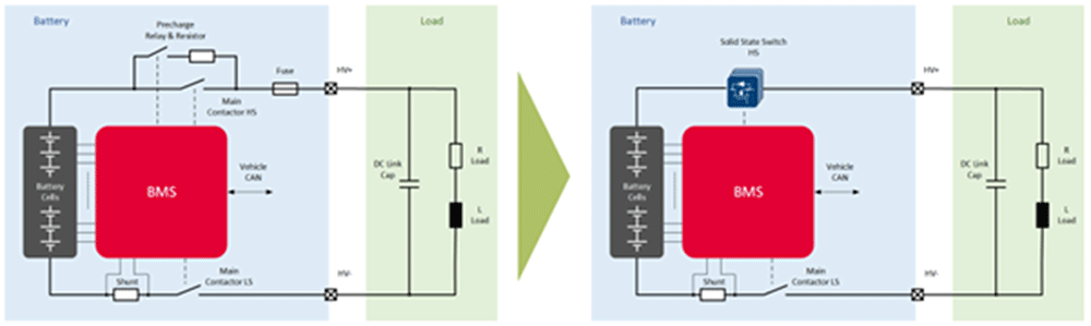
Figure 4. Replacing main contactor, precharge relay and melting fuse by a semiconductor switch.
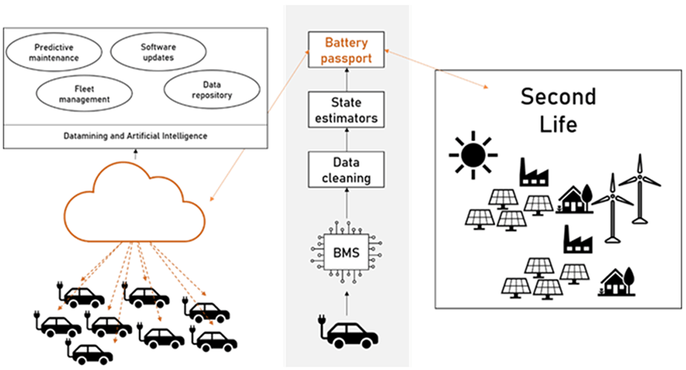
Figure 5. Real-time data flow from deployed vehicles to battery passport, and remote troubleshooting and additional services enabled in consequence.
Sustainable dismantling and recycling
In LIBERTY, a dismantling process with integrated semi-automated processes will be proposed. This improves dismantling efficiency and reduces safety risks, which become particularly important considering the higher voltage of the battery system to be developed (i.e. 800 V). Lithium recovery will be investigated by different metallurgical processes from black mass which was obtained after dismantling, thermal pyrolysis and mechanical separation. Increased lithium recovery will improve the overall recycling efficiency of lithium-ion batteries. LIBERTY should achieve a process for lithium recovery which consumes less energy and has less environmental impact.
Eco-design and life cycle performance
A comprehensive literature review of LCA studies3 for batteries for BEVs, integrating the consideration of circular economy (CE) scenarios was performed to i) identify and characterize the CE strategies studied in academic literature, ii) evaluate the reasons behind the variability in the environmental impacts and savings of the lithium-ion batteries (LIB) and iii) propose best practices and guidelines for the development of robust LCA studies of BEV batteries by integrating the CE criteria4. The main conclusions of the study are described in Picatoste et al.5, which can be summarized as follows. The best life-cycle management scenario includes a Lithium-Nickel-Manganese-Cobalt-Oxide (NMC) battery with a second-life cycle as stationary battery (repurposing) and recycling after the end-of-life. The efficient thermal management of the battery improves the lifetime/longevity, significantly reducing resource consumption and environmental impacts. Standardized battery components can facilitate maintenance, repurposing and recycling and direct cathode recycling could be the best recycling process to mitigate carbon emissions. However, a holistic analysis of the suitability of CE strategies is yet lacking. Building upon these findings, the importance and viability of the implementation of life-cycle-based CE design criteria in the development of the LIBERTY battery pack was explored. In Picatoste et al.6, it is concluded that the most important CE design criteria relates to the manufacturing stage of LIBs, as this stage presents greater flexibility for the integration of CE innovations, including innovations oriented at increasing the performance and quality of the final product by anticipating to new legislation requirements for BEVs. On the other hand, design criteria related to the end-of-life (EOL) management of LIBs showed lower implementation potential due to the perceived low influence of the battery designers and producers in the EOL management of the batteries. All these findings are currently being considered by the LIBERTY project which is developing a modular LCA of the battery and comparing the resulting performance with the benchmark battery.
Conclusion and future work
The LIBERTY project started in January 2021. Since then, the evolution of the project mainly focused on the definition of system level requirements, the test plan, and the consolidation of the battery pack design. The present paper briefly describes the main objectives of the project, the adopted methodology and many of the innovations currently being addressed by the LIBERTY project. As the component manufacture and testing activities advance in the upcoming months, further dissemination actions will be carried out and the main contributions to the academia and the scientific and automotive community will be published in future congress and journal publications.
Find out more on our website: https://www.libertyproject.eu/.









