1. Introduction
Hydrogen (H2) is a good carrier of clean energy, with a high heat of combustion (122 kJ·g−1) when compared to other fuels.1 Another advantage of H2 is that it can be sustainably produced from the degradation of organic matter using a microbial electrolysis cell (MEC).2 In MECs, electrons, CO2, and H+ are generated at the anode, while H+ is reduced at the cathode to form H2. However, the production of H2 in an MEC also has some drawbacks: (i) it is not a spontaneous process; therefore, it requires the application of a voltage through an external power supply or a potentiostat, and (ii) the reduction reaction of H+ to H2 has very slow kinetics. Consequently, a catalyst is necessary to carry out the reaction, which significantly increases the cost of the cells3.
According to the Nernst equation, a voltage of 0.14 V should be applied for the electrochemical reactions to take place under standard conditions (298 K and 1 bar). Still, in practice, a higher voltage, between 0.6 and 1.2 V is required to produce H2, due to the overpotential of the cell. Consequently, a catalyst was used to decrease the activation overpotential of the H2 production reaction, i.e. the overpotential of the cathodic reaction.4 The excellent catalyst used in MECs is Platinum (Pt) because of its high performance in such reactions. However, its high cost has stimulated the search for alternative catalysts5 such as non-noble transition metals. Thus, some studies have shown that catalysts based on other non-noble metals, such as Mo,6 Fe,7,8 or Ni, can9–13 be used for H2 production in MECs, in addition to cathodes based on alloys of these metals. Previous studies have shown that metal alloys perform well in H2 production; however,14–17 the performance of Pt as a catalyst has not been exceeded.
The challenge of this work was to evaluate alternative catalysts that are less expensive than Pt and to evaluate their effectiveness for H2 production. Moreover, these catalysts must be deposited on carbon materials with good electrochemical properties to be used as cathodic electrodes in cells for H+ reduction. For this reason, the materials selected were carbon cloth and carbon felt, two carbon-based supports with good properties for use as electrodes, in addition to being two of the most widely used cathode materials. Thus, different transition metals were used as catalysts, both individually and to create alloys with more than one metal; the catalysts tested were Cu100, Ni100, Ni85Mo15, Ni64Fe18Mo18 and Ni76Fe16Mo8. The subscript numbers correspond to the mole fractions of the individual metals. Likewise, two complementary strategies have been defined to deposit these metals on the electrode: electrodeposition and manual deposition,18 as both are the two most widely used and least costly techniques.
After obtaining the catalysts and depositing them on the corresponding cathodes, the final objective was to evaluate the performance of the cells and determine the real efficiency of the alloy-based catalysts versus the use of Pt as a catalyst. The performance of MECs was evaluated using a bioanode under more realistic conditions. To evaluate and characterize the different catalyst materials, different analytical and electrochemical techniques, such as Electrochemical Impedance Spectroscopy (EIS) and Linear Sweep Voltammetry (LSV), and optical microscopy techniques, such as Scanning Electron Microscopy (SEM), were used. Although these alloys have been tested previously, for the first time, they will be deposited on carbon cloth and carbon felt, comparing both materials. In addition, for the first time, both types of electrodes will be tested in electrochemical cells to observe their behavior under realistic conditions.
2. Materials and methods
2.1 Microbial electrolysis cell construction
Call and Logan19 first presented a cubic MEC (Figure S1). The MEC used in this work consisted of a 35 mL cubic cell consisting of a methacrylate body 4.4 cm long x 5 cm wide x 5 cm high height body and a glass cylinder (7.7 cm height × 2 cm diameter) placed hermetically at the top, where a gas collection bag was placed. The main body was assembled with two methacrylate side plates using O rings to prevent electrolyte leakage. These parts were held together using screws and wing nuts.20
The gas obtained was collected in a 100 mL gas bag containing a twist-type valve (Cali-5-Bond, Ritter) located at the end of the glass cylinder by piercing a septum placed at the end of the cylinder, which made the cell remain airtight.
A graphite fiber brush was used as the anode. On the other hand, the cathode was made of carbon felt or carbon cloth (Carbon Felt 3.18 mm thick 99.0%,
ThermoScientific Chemicals and Carbon Cloth Zoltek Fabrics Carbonized, Woven Fabric, Plain Weave 237 g·m−2), slightly modified with a catalytic layer on the inner side of the cathode.
The electrodes were connected to a power supply (Valleman Energy, LABPS3005DN). In addition, 10 Ω Rext was connected in series to monitor the cell current.
Cells were filled with 35 mL of fresh mineral medium and sodium acetate at a concentration of approximately 1.5 g·L−1. The mineral medium composition for all cells contained (per L of Milli-Q-water) 15.09 g Na2HPO4·2H2O, 2.06 g KH2PO4, 0.2 g NH4Cl, 4.0 mg FeCl2, 6.0 mg Na2S and 5 ml of nutrient solution, which contained per L: 1 g EDTA, 0.164 g CoCl2·6H2O, 0.228 g CaCl2·2H2O, 0.02 g H3BO3, 0.04 g Na2MoO4·2H2O, 0.002 g Na2SeO3, 0.02 g Na2WO4·2H2O, 0.04 g NiCl2·6H2O, 2.32 g MgCl2, 1.18 g MgCl2, 1.18 g MnCl2·4H2O, 0.1 g ZnCl2, 0.02 g CuSO4·5H2O, and 0.02 g AlK (SO4)2.18 All reagents were of analytical grade and supplied by Scharlau SL (Spain). The initial pH and conductivity of the cells were approximately 7.5 and 13 mS·cm−1, respectively. In addition, the cells were bubbled with nitrogen for 10 min to remove the dissolved oxygen from the medium.
2.2 Analytical methods and instrumentation
To monitor the cells, the composition of the cell medium was analyzed using different instrumental techniques. For this purpose, a sample of the mineral medium was taken at the beginning and the end of each cycle without exceeding 10% of the complete volume of the reactor. The cells were then filled with fresh mineral medium.
Acetate was analyzed using a gas chromatograph (Agilent Technologies, 7820-A) employing a DB-FFAB column, flame ionization detector, and He as the carrier gas.21
Some materials were studied and morphologically characterized using SEM to observe the electrodeposition of different metals and alloys on the electrodes. SEM measurements were carried out using a Merlin Zeiss microscope operated at 5 kV with an EDX detector (SEM-EDX) analysis system and Jeol JSM 6010 (JEOL, Ltd, Tokyo, Japan).22
Both electrodes were linked to a power supply at a 1.0 V potential. The voltage across each resistance was measured using a 16-bit resolution data-acquisition card (Advantech PCI-1716). AddControl software, programmed in LabWindows/CVI2021, was used for process control and data storage.23 H2, CH4, and CO2 were measured using a gas chromatograph (Agilent Technologies, 7820-A).
2.3 Electrochemical techniques
The different electrochemical techniques described in this section were used to study the behavior of the different catalysts. These techniques were applied in a three-electrode configuration and in a single methacrylate cell in all cases, employing the same anode for all catalysts. A commercial Ag/AgCl electrode (BioLogic) with KCl 3 M internal solution was used as a reference electrode, and the different cathodes were studied as working electrodes (WE).
2.3.1 Electrochemical impedance spectroscopy
EIS is a non-destructive technique used to determine the internal resistances, both ohmic and charge transfer, of the cell under study, as well as the value of the electrolytic double layer. Consequently, the measurements are helpful for gathering the performance information of both electrodes.24,25 Unlike other techniques, EIS allows measurements at equilibrium or steady state. A small sinusoidal alternating current (AC) of variable frequency was applied to measure the impedance of a circuit element or a complete cell, and the corresponding potential was measured as a function of frequency.
EIS analyses were performed in the frequency range of 100 kHz–10 mHz at the open-circuit potential. The amplitude was set to 1 mV to avoid detachment of the biofilm and to reduce disturbance to the steady-state conditions of the cell.22 In addition, acetate was added to prevent it from being the limiting factor, and nitrogen was sparged for 30 min to simulate the real conditions in the cell. The circuit used for fitting the results was a simplified version of the Randles circuit, without the Warburg element.26
2.3.2 Linear sweep voltammetry
LSV is a technique that performs a linear potential sweep from the lower potential limit to the upper potential limit, i.e., the technique consists of recording the intensity when a potential sweep is performed in a given direction at a constant speed of 10 mV·s−1.
The potential sweep applied to the cell was from −1.0 to −3.0 V, in 0.1 V intervals. A period of 1 min was used for current stabilization at each voltage. To analyze the different electrodes fabricated, LSV was performed under abiotic conditions to evaluate the catalytic efficiency of the cathode without the intervention of microorganisms. With this technique, it was possible to evaluate the performance of the catalyst because for the same applied potential, the intensity obtained by the abiotic electrode can be monitored. Thus, the electrode with the highest current intensity in absolute value, that is, that with the highest slope, showed the highest performance.
2.4 Manual deposition of different catalysts
To manufacture parts of the different cathodes used, different metals (Cu and Ni) were manually deposited on the two types of carbon-based materials, with a projected area of 7 cm2.
2.4.1 Manual Cu
100 deposition
A Cu100 catalyst was manually deposited using a knife or roller to spread the ink. To make the Cu ink, which was subsequently deposited, first, 6.6 ml of Milli-Q deionized water (Millipore, Billerica, MA, USA); 13.4 mL of ethanol and 0.2 mL of acetic acid were added in a beaker to obtain a total volume of 20.2 mL, and percentages of 33%, 66%, and 1%, respectively. This mixture can be stored in a dry place without light for one month so that it can be used to make different electrodes, because a small amount (≈ 8 mL) is used in one deposition.
Then, in a 5 mL beaker, 1 g of Cu nanoparticles (Sigma Aldrich, 25 nm nanoparticle size) was added to 2 mL of the above mixture. Thus, for each electrode, an ink batch was prepared with 4 g of Cu nanoparticles and 8 mL of the above mixture and homogenized. To this dispersion, 10 drops of the commercial solution Tween 20 (polysorbate 20) were added, and the mixture was sonicated in an ultrasonic bath for 30 min. The ink was homogeneously and continuously deposited on the surface of the entire electrode. The electrode was placed on a heating plate at a temperature of approximately 30–40 °C to accelerate the evaporation of the mixture during deposition.
At the end of the sonication, the ink was spread on the electrode with a roller or knife, and the entire electrode was covered. Finally, the electrode with the catalyst was left to dry overnight in a flask under nitrogen atmosphere at 100 °C to seal the deposition. The Cu100 electrode was ready for use the following day.
2.4.2 Manual deposition of Ni
100
One of the two depositions of the Ni100 catalyst was carried out manually on the carbon cloth electrode using a knife or roller to spread the ink. For this deposition, the same procedure as described in section 2.4.1 was followed, but Ni nanoparticles were used instead (Sigma Aldrich, average nanoparticle size <100 nm). The amounts of reagents used and the steps followed were identical to those used for the Cu deposition.
2.5 Electrochemical deposition of the different catalysts
Different metals (Cu and Ni) or alloys were electrochemically deposited on two types of carbon-based materials to fabricate different cathodes. A projected area of 7 cm2 is used in this study. The proposed metals were Fe, Ni, and Mo, and different alloys of these three metals because they are highly conductive metals and abundant in nature, which makes them accessible and inexpensive to scale up, unlike Pt.
A Gamry Instruments Interface 1010 potentiostat/galvanostat (model 25065) was used to perform electrodeposition. In all deposition baths, together with the reagents mentioned in each corresponding section, 0.15 moles of Na3C6H5O7 and 0.5 moles of NaHCO3 were added per liter. When the deposition bath was prepared, the electrode to be deposited, either the carbon cloth or carbon felt, was immersed in the bath and connected to the potentiostat acting as WE. A commercial graphite electrode was used as the counter electrode (CE) and Ag/AgCl(sat) was used as the reference electrode.
2.5.1 Electrodeposition of Ni
100
The electrode was immersed in a 1 L Ni deposition bath prepared by adding 0.250 mol of NiCl2. The bath was left to stir for 15 min, and then the pH was adjusted to 10.5 with 1 M NaOH. Finally, the electrode is immersed and connected to a potentiostat.
Electrodeposition was performed by chronoamperometry at a current of 50 A·m−2 for 3 h. The electrode was then disconnected from the potentiostat and allowed to dry overnight in a flask under nitrogen atmosphere at 120 °C. After the drying step, the electrode was washed with Milli-Q deionized water to remove excess Ni and then ready for use as a cathode.
2.5.2 Electrodeposition of alloys
For Ni85Mo15 electrodeposition, a 1 L deposition bath containing Ni and Mo was prepared: 0.213 mol of NiCl2 and 0.038 mol of Na2MoO4. The procedure described in section 2.5.1. followed, except that chronoamperometry for electrodeposition was performed at a current density of 100 A·m−2 for 6 h.
Similarly, the electrodeposition of Ni64Fe18Mo18 was performed by preparing 1 L of the deposition bath with Ni, Fe, and Mo: 0.160 mol of NiCl2. 0.045 mol FeCl3, and 0.045 mol Na2MoO4. The same procedure as for the Ni85Mo15 electrodeposition was followed, except that chronoamperometry for electrodeposition was performed at a current density of 200 A·m−2 for 6 h. Ni76Fe16Mo8 electrodeposition was performed by preparing a 1 L deposition bath containing Ni, Fe, and Mo: 0.190 mol of NiCl2, 0.040 mol of FeCl3, and 0.020 mol of Na2MoO4, followed by the same procedure as for Ni64Fe18Mo18.
3. Results and discussion
3.1 Abiotic electrochemical characterization
Before inoculating the corresponding cells, an abiotic study was conducted to determine the efficiency of the different cathodes and evaluate their performance in H2 production. For this purpose, LSVs of the carbon cloth electrodes with the different catalyst depositions were performed through a potential sweep from −1.0 V to −3.0 V (
Figure 1). The Ni64Fe18Mo18 alloy exhibited the best performance, as it exhibited the highest current intensity in absolute value for the same applied potential. Following the same reasoning, the Ni76Fe16Mo8, Ni85Mo15 electrodeposited, and Cu catalysts with manual deposition exhibited similar behavior. Conversely, the catalysts with the worst performance was Ni100 with manual deposition, followed by Ni100 electrodeposited. Consequently, Ni100 manual deposition was discarded from this study, not only because of its low performance, but also because of the high time required to perform each manual deposition of the catalyst.
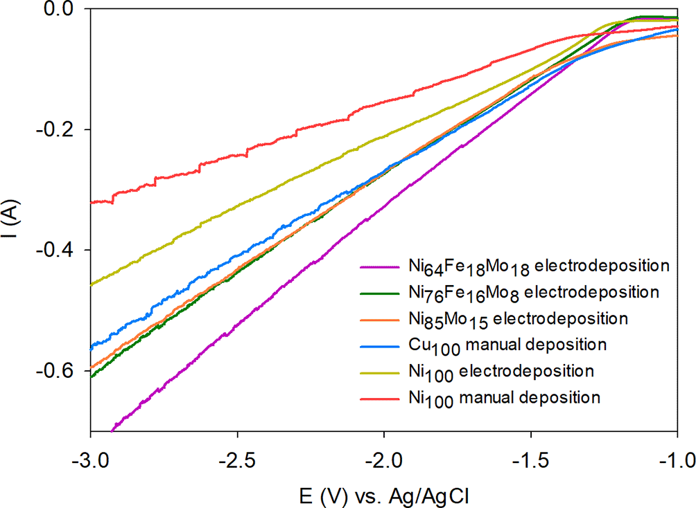
Figure 1. LSV of different catalyst depositions on carbon cloth.
Scan rate 10 mV·s−1.
In addition, the effect of using carbon cloth and carbon felt as base materials for the manufacture of electrodes was studied. The catalysts studied were Ni alloys and metallic Ni electrodeposited on carbon cloth and carbon felt electrodes.
The internal resistance of each cell was studied using two different WE support materials by performing abiotic EIS. The EIS results (
Figure 2) and the parameters extracted from the Randles circuit adjustment (
Table 1) show that all carbon felt and carbon cloth cathodes modified with all catalyst electrodepositions presented a similar RΩ, which is related to the fact that the electrolyte and the cell design are the same in all cases. In contrast, Rct, which is related to the ease of electron flow, i.e., the ease with which the WE carried out the electrode reaction, was very variable from one electrode to another. In general, all carbon felt electrodes showed lower Rct values than the carbon cloth electrodes for a given catalyst. Therefore, carbon felt electrodes offer fewer limitations on electron transfer (small Rct) and consequently provide a higher electron transfer rate. Thus, carbon felt WEs performed better than carbon cloth WEs if they were modified with the same catalyst.
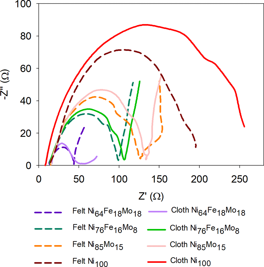
Figure 2. Abiotic EIS using the different types of WE: carbon cloth electrode and carbon felt with the different Rext catalysts subsequently fitted to Randles’ simplified circuit: RΩ·(Rct·Cdl).
Frequency ranges from 100 kHz to 10 mHz.
Table 1. Resistances RΩ and Rct obtained from Randles’ equivalent circuit (RΩ·(Rct·Cdl)) in cells with felt and carbon cloth cathodes with the various electrodeposited catalysts.
Frequency ranges from 100 kHz to 10 mHz.
| Material | Internal resistance RΩ (Ω) | Charge transfer resistance Rct (Ω) |
|---|
| Carbon felt Ni64Fe18Mo18 | 13.6 | 45.6 |
| Carbon cloth Ni64Fe18Mo18 | 16.4 | 60.2 |
| Carbon felt Ni76Fe16Mo8 | 14.9 | 98.9 |
| Carbon cloth Ni76Fe16Mo8 | 14.4 | 107.3 |
| Carbon felt Ni85Mo15 | 15.0 | 126.7 |
| Carbon cloth Ni85Mo15 | 15.9 | 134.2 |
| Carbon felt Ni100 | 14.7 | 195.3 |
| Carbon cloth Ni100 | 8.7 | 255.9 |
Table 1 shows that the carbon felt electrode with the Ni64Fe18Mo18 catalyst had the lowest Rct followed by the carbon cloth electrode with the same catalyst. The results were in concordance with those obtained by LSV, where Ni64Fe18Mo18 was the catalyst with the highest current intensity in absolute value obtained (
Figure 1). Moreover, comparing the Rct of all the WE, it was found that the electrodes modified with the Ni64Fe18Mo18 catalyst, both using cloth and felt, showed a much lower Rct compared to all other catalysts (
Table 1), followed by the WE with the Ni76Fe16Mo8 catalyst. This may be due to the fact that this alloy has a higher electrical conductivity than the others or at least makes it easier to transfer electrons from one electrode to another. The results also show that the carbon felt provided always had a lower charge transfer resistance than the carbon cloth for all the deposited materials tested.27 This is due to the fact that the carbon felt has a larger surface area than the carbon cloth, due to its thickness. The electrode with the highest Rct corresponds to the carbon cloth WE modified with Ni100, which presents an Rct almost six times higher than that obtained with the Ni64Fe18Mo18 catalyst on the carbon felt WE. It should be noted that a higher difference in charge transfer resistance was obtained for the carbon cloth with respect to the carbon felt covered with both the Ni100 catalysts (31%) and the Ni64Fe18Mo18 catalyst (32%). The trend observed in the behavior of the catalysts is consistent with the results obtained using the LSV technique for WE carbon cloth modified with the same catalysts. It can be concluded that carbon felt was the best support material for WE, while Ni64Fe18Mo18 was the most efficient catalyst, according to the LSV and EIS results.
3.2 Cathode surface morphology characterization
SEM optical microscopy was used to study the distribution of metals on the cathode surface for the electrodeposition of different alloys on the two types of bare electrodes, both on carbon cloth and carbon felt.
Figure 3 shows SEM images of the carbon cloth electrodes at 20 × magnification covered with Ni64Fe18Mo18 (
Figure 3a), Ni76Fe16Mo8 (
Figure 3b), Ni85Mo15 (
Figure 3c), and Ni100 (
Figure 3d).
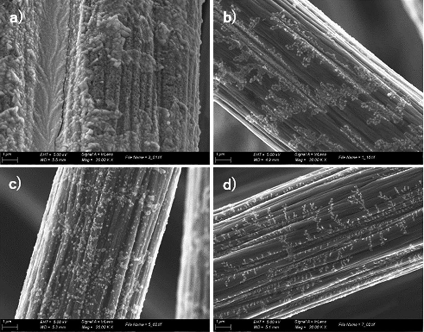
Figure 3. SEM images at 20 k magnification of carbon cloth WE covered with a) Ni64Fe18Mo18 catalyst, b) Ni76Fe16Mo8 catalyst, c) Ni85Mo15 catalyst, and d) Ni100.
When comparing the surface of the carbon cloth with the different catalysts, it is observed that there is a part of the electrode that is not covered with the catalyst in all cases, i.e. there are parts of the electrode where the catalyst has not been electrodeposited. The electrode with the most covered surface was the electrode with the Ni64Fe18Mo18 catalyst (
Figure 3a), followed by the electrode with the Ni76Fe16Mo8 catalyst (
Figure 3b). On the other hand,
Figure 4 shows the SEM images of the carbon felt electrodes at 20 k x magnification covered with Ni64Fe18Mo18 (
Figure 4a), Ni76Fe16Mo8 (
Figure 4b), Ni85Mo15 (
Figure 4c) and Ni100 (
Figure 4d). In the case of carbon felt, all the catalysts were homogeneously electrodeposited on the entire electrode surface.
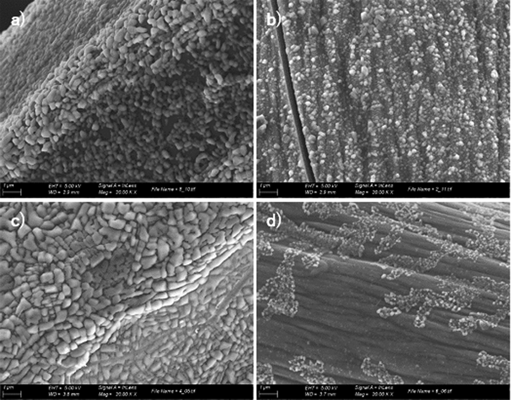
Figure 4. SEM images at 20 k magnification of carbon felt WE covered with a) Ni64Fe18Mo18 catalyst, b) Ni76Fe16Mo8 catalyst, c) Ni85Mo15 catalyst, and d) Ni100.
In addition,
Figure 3 shows that the electrodeposition on the carbon cloth WEs creates branching on the electrode fibers and, conversely, with the carbon felt, the catalyst deposition is more granular (
Figure 4), causing the electroactive area of the electrode to increase because of its 3D structure as a catalyst. In addition, Figure S2 and S3 show the SEM images of the carbon cloth and carbon felt, respectively, at 1 k x magnification for the same catalysts shown in
Figures 3 and 4. Figure S2c shows that the Ni85Mo15 catalyst did not completely coat the fibers. A similar behavior was observed for the Ni100 catalyst (Figure S2d), where a branching coating was observed, and a less homogeneous deposition was observed compared to the Ni64Fe18Mo18 and Ni76Fe16Mo8 catalysts. Figure S3 shows that in contrast to Figure S2, the least homogeneous depositions with carbon felt were Ni76Fe16Mo8 and Ni100. Interestingly, the catalyst deposition of Ni100 on both carbon materials was neither continuous nor homogeneous. The difference between the Ni100 coatings could be because they were made at a lower current density and for half the time of the alloys studied. A branching electrodeposition was produced without completely coating the carbon fibers of both materials, which is in line with the Ni metal catalyst, which exhibited the worst performance in catalysis for H2 generation (
Figure 1).
The results from the SEM images were in accordance with the LSV and EIS results. In terms of electrochemical efficiency, the deposition of the catalyst on the carbon felt electrode offered better results than the deposition on the carbon cloth. SEM images showed that the deposition of alloy catalysts on carbon felt was more granular, the coating was more homogeneous, and the electrode fibers were completely covered, thus increasing the catalytic surface area where the electrochemical reaction takes place. The carbon felt electrode has a more geometric surface and more fibers than the carbon cloth electrode, where the alloy can be electrodeposited. In addition, carbon felt is a carbonaceous material with a larger surface area and is also a good and inexpensive conductive material, making it suitable for use as a cathode electrode. Therefore, the increase in the catalyst performance observed from the LSV and EIS results when a carbon-felt WE was used can be attributed to the increase in the geometric area, which facilitates a higher degree of metal electrodeposition. Overall, electrodeposition on carbon felt led to a higher yield of H2 production.
Comparing all the catalysts used in this study, it can be concluded that the catalyst with the best performance corresponded to the carbon felt electrode with the Ni64Fe18Mo18 catalyst. This performance can be related to several factors, such as the homogeneous electrodeposition of the catalyst on the WE (
Figure 4) and the composition and ratio of metals in the alloy, which increases the efficiency of the catalyst, making it possible to favor the production of H2 and increase the efficiency of the WE modified with the Ni64Fe18Mo18 catalyst.
3.3 Evaluation of cell performance
The biotic evaluation of the catalysts on the MECs was performed during the three weeks of operation. Six electrodes were tested: three carbon felt and three carbon cloth (CC) electrodes electrodeposited with Ni85Mo15, Ni64Fe18Mo18 and Ni76Fe16Mo8. The Ni100 electrode was discarded based on the results of abiotic electrochemical characterization.
Figure 5 shows the current densities obtained during the three weeks of operation. The Ni64Fe18Mo18 cathode exhibits the best performance. The highest current density was obtained for the carbon felt electrode, with a maximum of 1.1 mA·cm−2, followed by the carbon cloth electrode with the same catalyst (1.0 mA·cm−2). Both cells generated a similar amount of gas, 1.2 m3m−3d−1 for the cell with the carbon felt electrode and 1.1 m3m−3d−1 for the carbon cloth electrode. As an alternative to the Ni64Fe18Mo18 catalyst, the WE covered with the Ni76Fe16Mo8 catalyst followed the former in terms of performance. In this case, a similar current density was obtained for both the carbon felt electrode and the carbon cloth electrode with the Ni76Fe16Mo8 catalyst (
Figure 5); however, in the last cycle, the electrode with carbon felt provided the highest current density. This result is consistent with that obtained in abiotic experiments (see Section 3.1). This could be attributed to the slightly larger geometric area of the carbon felt. These cells generated 0.9 ± 0.2 m3m−3d−1 of gas for the carbon cloth electrode cell and 1.1 ± 0.1 m3m−3d−1 for carbon felt electrode cell.
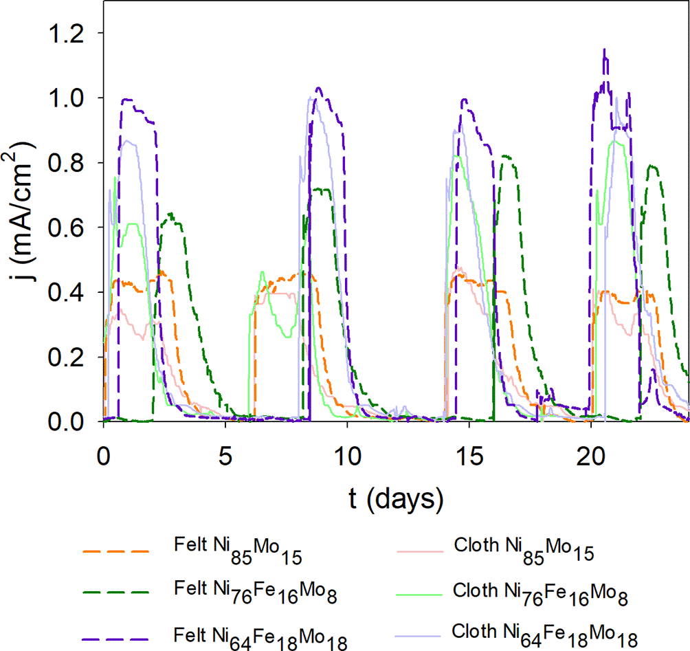
Figure 5. Current density of the cells with the six cathodes studied and the different catalysts.
Finally, the catalyst exhibited the worst biotic performance was the Ni85Mo15 catalyst. In this case, similar performance was also observed for the carbon felt and carbon cloth catalysts, even though the carbon felt electrode produced a higher current density (maximum 0.5 mA·cm−2) compared to the carbon cloth electrode (maximum of 0.4 mA·cm−2). The H2 production was 0.8 m3m−3d−1 with the carbon felt electrode and 0.5 m3m−3d−1 with the carbon cloth electrode. The amount of gas produced in each cell was much lower than would be expected when the cells were operating at 100%. It is likely that the cells suffered from gas leaks and possible gas recirculation, which reduced the amount of H2 that was produced.
To properly evaluate the behavior of the H2 catalysts in MECs, their performance was compared with that of other electrodeposited catalysts studied in the literature, other than Pt, because the main objective of this work was to find an alternative catalyst to replace Pt in the H2 production electrode produced by the H+ reduction reaction. A current density of 0.9 mA·cm−2 was reported in MECs with electrochemically deposited NiW catalyst, which is 25% lower than in the case of the Ni64Fe18Mo18 catalyst in carbon felt WE.14 Other studies have used Ni foam as a catalyst instead of a Ni alloy. In this case, although the cell dimensions were smaller, the Ni64Fe18Mo18 catalyst electrodes studied here achieved up to 20% higher current density.28 A maximum volumetric H2 production of 0.76 m3m−3 day−1 was reported using nickel 625 as the cathode, which was significantly lower than that of our best catalyst, which had a maximum volumetric H2 production rate of 1.2 m3m−3 day−1. Finally, Lee et. al29 reported the use of a carbon felt electrode without any metal for H2 production, obtaining a current density of 0.33 mA·cm−2, 73% lower than the maximum current density obtained with the carbon felt WE and Ni64Fe18Mo18.
It can be concluded that the Ni64Fe18Mo18 catalyst with carbon felt WE could be used in MECs because of its higher performance compared to other catalysts used for H2 production. It should be emphasized that the study of these catalysts needs to be extended to a longer operation time to stabilize the maximum current density and to more precisely define the advantages and limitations of using these metallic alloys as catalysts.
3.4 Economic study of the different catalysts
To properly evaluate the different catalysts and check their potential for full-scale implementation of MECs, a cost study of each type of alloy was carried out. This study presents a preliminary assessment of the total costs estimated from the cost of the materials needed at the laboratory scale. Obviously, a proper marketability analysis that is beyond the scope of this work is warranted to scale up these results.
The analysis was performed using two types of bare electrodes used in this study. In the case of the carbon felt, Carbon Felt 3.18 mm thick 99.0% (ThermoScientific Chemicals) was used (99.36 €·m−2) whereas Zoltek Fabrics (Carbonized Woven Fabric, Plain Weave 237 g·m−2) was used in the case of the carbon cloth (38.09 €·m−2). As for the preparation of the technique, 13.4 mL of ethanol, 0.6 ml of Milli-Q water, and 0.2 mL of acetic acid, were used in all cases, leading to an equivalent cost for all of electrodes manufactured.
On the other hand, some reagents change for each catalyst used: to perform the manual Cu deposition, for one electrode it is necessary to use 4 g of Cu (Cu nanoparticles (Sigma Aldrich), 25 nm nanoparticle size) and 10 drops of the commercial solution Tween 20. A total of 0.5 mL of Tween 20 is needed, assuming that one drop is 0.05 mL. For the manual deposition of Ni100, the procedure and reactants were exactly the same as those for the manual deposition of Cu100, except that Cu was substituted for Ni.
For the electrodeposited catalysts, all solutions required the use of 0.16 mol Na3C6H5O7 and 0.5 mol NaHCO3, added per 1 L. Specifically, for the electrodeposition of Ni100, 0.250 mol of NiCl2 was needed. For the Ni85Mo15 electrodeposition, 0.213 mol of NiCl2 and 0.038 mol of Na2MoO4 were used. For the Ni64Fe18Mo18 electrodeposition, 0.045 mol FeCl3, 0.160 mol NiCl2, and 0.045 mol Na2MoO4 were required. Finally, 0.040 mol of FeCl3, 0.190 mol of NiCl2 and 0.020 mol of Na2MoO4 were used for the Ni76Fe16Mo8 electrodeposition.
The electrical cost for electrodeposition was also considered, considering the unit cost of electricity (
Table 2), a potentiostat power requirement of 2 kWh, and the time required for the electrodeposition of Ni (3 h) or the rest of the catalyst electrodeposition (6 h).
Table 2. Unit costs of different materials used for different catalysts ink.
| Material |
Unit costs |
|---|
| Carbon cloth | 38.09 €·m−2 |
| Carbon felt | 99.36 €·m−2 |
| Ethanol | 41 €·L−1 |
| Milli-Q water | Negligible |
| Acetic acid | 133 €·2.5 L−1 |
| Cu nanoparticles | 76 €·5 g−1 |
| Tween 20 | 36.90 €·100 mL−1 |
| Ni nanoparticles | 73 €·5 g−1 |
| Na3C6H5O7 | 64.80 €·1 kg−1 |
| NaHCO3 | 47.80 €·500 g−1 |
| NiCl2 | 279 €·250 g−1 |
| Na2MoO4 | 78.90 €·100 g−1 |
| FeCl3 | 46.0 €·100 g−1 |
| Electricity | 0.090 €·kWh−1* |
The unit cost of these materials is shown in
Table 2, where Milli-Q water has a negligible cost.
Table 3 shows the cost of the materials for the construction of electrodes for each technique based on the quantity and cost of each material used. It should be noted that the carbon felt electrode is more expensive than the carbon cloth electrode, but it provides better results and is more homogeneous. In fact, the costs normalized by the H2 production in
Table 3 show that carbon felt leads to lower costs and is therefore more cost-effective for use in electrochemical cells. Besides, it can be seen that manual depositions are more expensive than electrodeposits, as well as showing worse results. Among the electrodeposits, the most economical is Ni76Fe16Mo8 followed by Ni64Fe18Mo18, Ni100 and Ni85Mo15. When normalized by H2 production, these prices were the most economical is Ni64Fe18Mo18, followed by Ni76Fe16Mo8 and Ni85Mo15.
Table 3. Construction costs of cathodes and normalized costs based on the H2 production of the different depositions.
| Deposition | Cathode cost (€) |
H2 production (m3m−3d−1) |
Normalized cost (€(m3m−3d−1)−1) |
|---|
| Carbon felt | Cu Manual | 61.8 | - | - |
| Ni Manual | 58.7 | - | - |
| Ni100 electrodep. | 43.7 | - | - |
| Ni85Mo15 electrodep. | 45.1 | 0.8 | 56.4 |
| Ni76Fe16Mo8 electrodep. | 42.3 | 1.1 | 38.5 |
| Ni64Fe18Mo18 electrodep. | 42.8 | 1.2 | 35.7 |
| Carbon cloth | Cu Manual | 61.5 | - | - |
| Ni Manual | 58.4 | - | - |
| Ni100 electrodep. | 43.4 | - | - |
| Ni85Mo15 electrodep. | 44.8 | 0.5 | 89.6 |
| Ni76Fe16Mo8 electrodep. | 42.0 | 0.9 | 46.7 |
| Ni64Fe18Mo18 electrodep. | 42.5 | 1.1 | 38.6 |
Considering the quantities of each material used, the cost of the materials for the construction of electrodes for each technique would be 61.5 € per cathode for manual Cu deposition and 58.4 € for manual Ni deposition, whereas for electrodeposition techniques it would be 43.4 € for Ni100, 44.8 € for Ni85Mo15, 42.5 € for Ni64Fe18Mo18 and 42.0 € for Ni76Fe16Mo8 per cathode manufactured. It is worth mentioning that the absolute costs of materials are unrealistic from an industrial production scale, as well as biased by market fluctuations and the variability of materials. However, benchmarking at the lab scale can shed light on the relative viability of each technique.
In general, manual deposition is more expensive and less efficient than electrodeposition. Therefore, manual deposition could be discarded in the future. Electrodeposition, in addition to being more economical, offers better current density results and more homogeneous electrode modification. In addition, all electrodepositions have similar costs per electrode, with Ni76Fe16Mo8 and Ni64Fe18Mo18 being the cheapest and best-performing catalysts, respectively. Thus, considering the economic and performance factors, electrodeposition of Ni64Fe18Mo18 is the most profitable.
Under these considerations, Ni64Fe18Mo18 electrodeposition using carbon felt was found to be the most economical alternative, considering its cost and performance.
The economic comparison with electrodes with Pt ink, which is the most common, would be complicated, as the conditions must be the same. Commercial Pt ink has previously been used by the research group,30 but because the deposition conditions of the catalytic ink and the cell are different, a direct comparison of the associated costs could not be made.
4. Conclusions
In this study, the use of different catalysts for H2 production in MECs, namely Cu100, Ni100, Ni85Mo15, Ni64Fe18Mo18 and Ni76Fe16Mo8, was evaluated. The WEs were modified using two complementary strategies, manual deposition and electrodeposition, and two carbon materials, carbon cloth and carbon felt, were used.
All the catalysts were biotically characterized, and it was observed that the catalysts with manual deposition had worse performance than those with electrodeposition. EIS and LSV results during the characterization of the cells operating in abiotic mode showed that the electrode with electrodeposited Ni100 had worse performance than the other catalysts.
The performance of biotic MECs showed that the catalyst that provided the highest performance was Ni64Fe18Mo18 on carbon felt WE, obtaining a current density of 1.2 mA·cm−2, similar to the electrode with the same catalyst but deposited in carbon cloth (1.1 mA·cm−2). These catalysts achieve over 50% of the current density of Ni85Mo15 (0.4 mA·cm−2 with carbon cloth and 0.5 mA·cm−2 with carbon felt). Ni76Fe16Mo8 shows 1.1 ± 0.1 mA·cm−2 with carbon felt and 0.9 ± 0.2 mA·cm−2 with carbon cloth.
Although the results obtained in terms of the current intensity are similar to those found in the literature, the volume of H2 obtained is much lower than expected. Therefore, it can be concluded that the cells probably had gas leaks because the operation time was too short for the H2-competing microorganisms to grow.
However, taking into account the cost of manufacturing the electrodes with different depositions of Ni76Fe16Mo8 electrodeposition in carbon cloth provided the lowest cost for their construction, whereas Ni64Fe18Mo18 electrodeposited in carbon felt showed the lowest cost of the materials with respect to hydrogen production.
Ethics and consent
Ethical approval and consent were not required.









