Introduction
The certification of photovoltaic (PV) products is traditionally built around mainstream, standardised modules and high-volume product families. As a result, current certification frameworks are poorly suited to the emerging field of integrated photovoltaics (IPV), where mass-customisation introduces variability in the bill of materials, dimensions, shapes, and power output. Certifying every possible configuration is too costly and time-consuming; for example, IEA PVPS Task 151 notes that achieving full PV certification according to IEC standards requires four to six months for a single product, assuming no testing issues, and this timeline does not include country-specific BIPV requirements. Semi-fabricates (SFs), partially processed PV components central to the Mass-Customisation 2.0 (MC2.0) concept,2 further complicate certification, as they often lack junction boxes, mechanical supports, or other elements required for complete PV qualification. Conversely, applying full PV certification to finished IPV products can be excessive, particularly for applications with limited exposure to stressors (e.g., SFs inside insulating glass units). Overlapping PV and construction regulations frequently lead to duplicated testing, increasing costs without improving safety. These challenges highlight the need for a less expensive, more flexible, targeted certification pathway that can accommodate variability without compromising reliability.
In this article, we propose an alternative certification framework in which testing responsibilities are distributed between the SF and the IPV end-product manufacturers: SFs undergo pre-testing for aspects relevant to their level of completion, while tests that cannot be meaningfully performed at the SF stage are carried out on the final IPV product. Developing such an approach requires consideration of multiple layers of normative and regulatory requirements. We therefore reviewed conventional PV standards, BIPV-specific guidelines, and construction regulations at both the European and national levels for key MC2.0 markets (Italy, The Netherlands and Switzerland), complemented by insights from IEA-PVPS Task 15. The Task 15 report “Advancing BIPV Standardization: Addressing Regulatory Gaps and Performance Challenges”1 highlights the current fragmentation of certification requirements and calls for harmonisation across the construction sector to support BIPV adoption. One of the conclusions of the report is that helping manufacturers identify suitable test schemes can significantly reduce the burden of safely bringing products to market. This also underpins the rationale for our approach.
Reducing unnecessary retesting is a central objective. The IEA-PVPS Task 15 report1 provides a very inspiring example in the context of aging tests for BIPV applications, where a consolidated procedure reduced the required number of test modules from sixteen to twelve by combining overlapping stress sequences. This demonstrates that a thorough analysis of failure modes and associated stressors can yield more efficient qualification strategies while preserving safety. Similar questions arise when attempting to certify IPV products simultaneously as building components and PV modules:
• Which tests or test sequences are essential for each product family?
• Can some sequences be merged or applied at the SF level?
• Which tests are optional but provide extra quality or reliability guaranties to the stakeholders?
To ensure that the proposed certification pathway aligns with real-world needs, we conducted a broad stakeholder analysis. The stakeholders relevant to the BIPV sector were grouped into four key domains (
Figure 1): (1) the certification industry, including European, national, and regional regulatory bodies working within IEC and EN frameworks; (2) IPV manufacturers, including cell, module, and end-product developers; (3) the research sector, comprising PV institutes and IEA Task 15 experts; and (4) the construction sector, including architects, façade manufacturers, developers, and insurers whose acceptance is essential for market integration. Their feedback helped us identify the current challenges and opportunities for combined testing schemes bridging construction and PV standards.
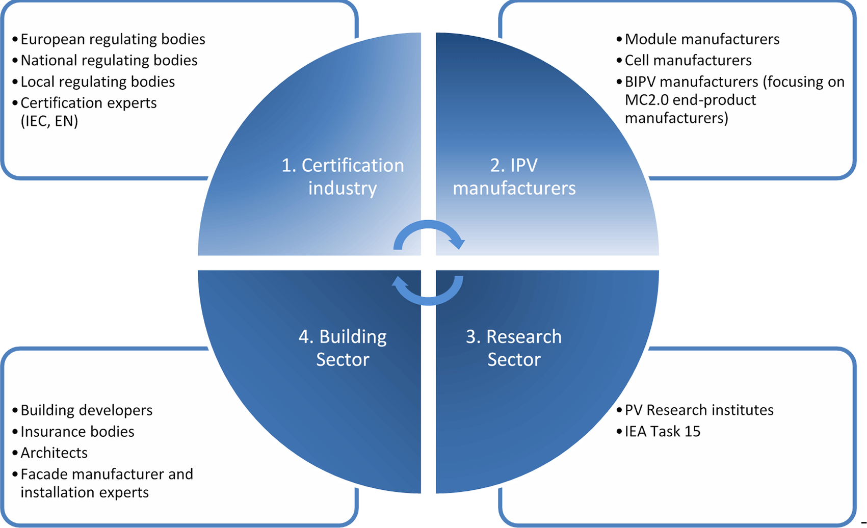
Figure 1. Mapping of relevant stakeholders.
Finally, to define both SF and product families, we revisited the requirements and design guidelines established at the onset of MC2.0. This formed the basis for a workflow that harmonises certification strategies, technical constraints, regulatory demands and market needs. The resulting framework supports a vision where specialised manufacturers produce large volumes of customisable SFs that feed into diverse IPV product families. Such flexibility is particularly critical for building-integrated PV (BIPV) applications, where tailored solutions are essential to wider adoption.
Methodology
In this article we propose an alternative certification framework that distributes PV testing between SFs (where possible) prior to integration, and the IPV end-product for tests that require components, attachments or integration into elements not present in the SFs. Additionally, this framework helps define and certify product families (groups of products with limited variations) instead of certifying each possible variation.
The process begins with defining the final product or product family, establishing its core requirements, design specifications, intended market, and overall functional application. Once the product vision is clear, the next step is to select the relevant product standards that apply to its category and use-case. Building on this, the process proceeds with identifying specific standard requirements across different regions and industries to ensure full regulatory and commercial compliance. In parallel, an end-product Failure Mode and Effects Analysis (FMEA)3 is drafted to map out potential risks and determine the relevant tests and standards, ultimately ensuring a robust and compliant product. The FMEA addresses critical risks across three levels: the SF, the complete product, and the interfaces between them. This step can also help product manufacturers that want to provide extra guarantees on reliability. Finally, boundary conditions, such as environmental stress levels (e.g., based on climate), are established, and certification pathways for different product families are outlined. The workflow is presented in
Figure 2.
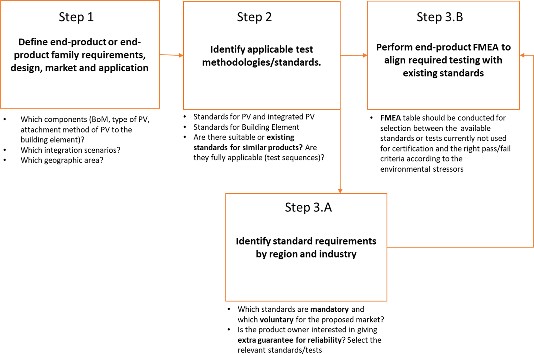
Figure 2. Workflow for certification identification process.
Identification of IPV product families based on semi-fabricate and application type
IPV products were grouped into distinct “families” based on their associated semi-fabricates (SFs) and their intended application. The key terms used for this classification are defined below:
•
Semi-fabricate (SF): A PV cell system configuration in its intermediate stage, before integration into the final IPV product.
•
End-product: The completed IPV system designed for a specific application and incorporating a defined SF configuration.
•
Product family: A group of end-products intended for the same application and built using similar types (e.g. similar bill of materials) of SFs.
An overview of this multi-level classification is shown in
Figure 3. To reflect the differing functional and regulatory demands of various applications, IPV product families were separated into two main categories: Insulating Glass Unit (IGU) BIPV products and façade or roof-tile BIPV products used as building cladding. Each category faces distinct performance, safety, and market requirements.
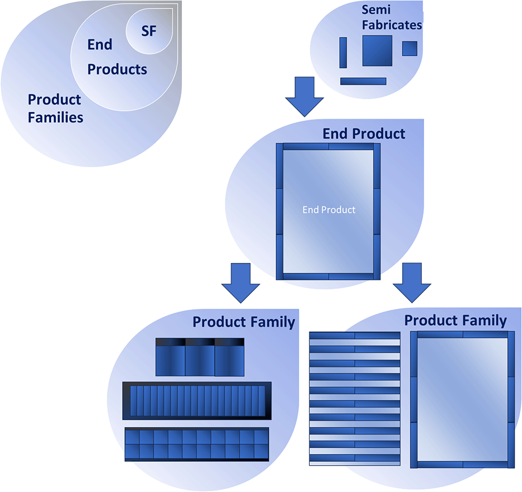
Figure 3. Multi-level classification of the Semi-Fabricates (SFs), end-products and product families.
Based on these definitions, we analysed the requirements applicable to each product family within the European context, focusing specifically on the Swiss, Italian, and Dutch markets. These requirements encompass CE-marking obligations, insurance expectations, and market-specific conditions that must be met for successful commercial deployment.
Current status of BIPV related standards
In the domain of photovoltaic and building-integrated glazing technologies, a coordinated group of international standards defines the optical characterisation, performance requirements, and lifecycle conformity of both conventional glazing and laminated photovoltaic glass. ISO 9050:20034 establishes the foundational methodology for quantifying light transmittance, solar direct transmittance, total solar energy transmittance, ultraviolet transmittance, and related glazing factors, forming the basis for thermal, daylighting, and energy modelling of building envelopes. Its forthcoming replacement, ISO/DIS 9050,5 modernises this framework by redefining the scope to focus on the luminous and solar characteristics of glazing, and updating terminology and calculation procedures to better reflect current glazing technologies and performance evaluation practices in the built environment. Complementing these optical/energetic standards, ISO/TS 18178:20186 provides comprehensive requirements for appearance, durability, mechanical and electrical safety, test methods, and designation of laminated solar photovoltaic glass intended for construction applications, offering a unified approach for BIPV products that must simultaneously meet architectural glazing and PV-module performance criteria. To support long-term reliability and ensure continued compliance following design modifications, ISO/TS 21486:20227 specifies the retesting requirements for laminated solar PV glass, outlining mandatory verification procedures when changes occur in glass composition, interlayers, solar cell technologies (crystalline or thin-film), interconnectors, or terminations, thereby safeguarding performance consistency and safety throughout the product lifecycle. Structural safety of BIPV products in project conditions (final dimensions, supporting system, wind zone, snow zone, height of the building, air temperatures and solar irradiance, etc.) is assessed according to EN 16612,8 FprEN 19100 series (currently in the stage of the Formal Vote) or according to national guidance documents and standards, e.g. NF DTU 39,9 NEN 260810 and DIN 18008 series.11
EN 50583–1:201612 is a European standard that defines the requirements for BIPV modules when they are used as construction products. It focuses on the properties of PV modules relevant to essential construction requirements under the Construction Products Regulation (CPR 305/2011)13 and the applicable electro-technical requirements under the Low Voltage Directive14 and relevant CENELEC standards. In particular, it specifies how BIPV modules must meet building-related performance expectations, such as mechanical resistance, fire safety, weather protection, and durability, while also addressing their electrical safety and functionality as photovoltaic generators. The standard applies only to BIPV modules (not concentrating PV or building-attached PV) and covers modules that are designed to be integrated into the building envelope (façades, roofs, shading elements, etc.), but it does not address the mounting structures, which are included in EN 50583–2.15 It is intended for manufacturers, system designers, planners, installers, testing bodies, and construction authorities, and references a broad range of international standards, technical reports, and guidelines relevant to glazing and PV applications. A newer version of this standard is under development, where harmonisation for multiple EU countries was attempted. However, harmonisation is challenging, since the standard refers to the Low Voltage Directive, which is not a regulation, but a directive, meaning that BIPV must comply with the national regulations for construction products. Considering IEC standards, the respective standard is IEC 63092 (−1 and − 2)16,17 (based on EN-50583 and adapted for international application), which mainly describes the requirements for BIPV, however, it mainly includes guidelines, it is not a testing standard, and also refers to the IEC PV related standards, IEC 6173018,19 and IEC 61215,20,21 and the CPR.13
Retesting of BIPV
BIPV requires flexibility in terms of sizes and material choices, and when such design or material modifications occur, IEC TS 6291522 provides the formal framework for determining how PV modules must be retested to maintain type approval, design qualification, and safety certification. The standard establishes a uniform approach for evaluating any change from the originally assessed PV module design, covering both wafer-based crystalline silicon technologies and thin-film modules, and lists typical modifications along with the corresponding retest requirements derived from relevant test standards. In its 2023 second edition, IEC TS 6291522 updates its references to IEC 6121520,21 and IEC 61730,18,19 introduces retesting requirements for new tests such as dynamic mechanical load (MQT 20) and potential-induced degradation (MQT 21), integrates component-level standards (IEC 62788–123–28 and IEC 62788–2 series29), and includes a comprehensive matrix summarising retesting needs for each type of design or material change, ensuring that evolving BIPV designs remain compliant with safety and reliability expectations. A PV module manufacturer who targets BIPV markets should consider certifying their largest possible product size for the most failure-prone material combination and attachment scenarios. In case the largest product is too large to be certified, due to technical difficulties, a representative sample should be considered.
Fire safety
Fire safety for BIPV follows three regulatory levels. At Level 1, the EU CPR13 and national construction regulations in EU Member States and Switzerland define the fundamental legal obligations for construction products. At Level 2, harmonised EN standards for construction products and IEC/EN standards for PV components ensure that BIPV elements meet structural and electrical requirements. At Level 3, products undergo performance classification, mainly through the Reaction-to-Fire system (EN 1350130,31), which assesses fire resistance, flame spread, smoke production, and flaming droplets. Results are expressed in the Declaration of Performance (DoP) and shown through CE marking, which confirms CPR compliance but does not, in itself, guarantee safety.
A crucial distinction is that performance does not equal safety. Performance reflects how a product behaves in accordance with harmonised standards or European Technical Assessments (ETAs)32 and is expressed through declared values, classes, or levels in the Declaration of Performance and Conformity (DoPC).33 The EU imposes no minimum performance thresholds. It only requires transparent declaration. Safety, however, is determined at the national level and depends on the building context, intended use, declared performance, product documentation, and national rules. Thus, CE marking is not a safety approval, but a statement of conformity with the CPR.13 Real safety depends on proper use within national regulatory frameworks.
Fire-safety objectives in buildings focus on preventing ignition, limiting fire spread, ensuring material compatibility, enabling safe occupant evacuation, and supporting safe operations for firefighting teams. Buildings must minimise ignition risks from materials, electrical systems, or building functions, limit fire spread across assemblies and integrated systems such as BIPV and ensure that materials do not interact in ways that increase fire hazards. At the same time, safe evacuation routes and structural stability must be preserved to protect occupants and emergency responders.
A comprehensive fire-safety assessment requires analysing multiple ignition scenarios.34 These include Case A, ignition due to radiation from an adjacent fire, Case B, ignition from external flames, embers, or heat sources, Case C, internal ignition caused by electrical faults, appliances, or human activity, Case D, ignition on the rear side of PV modules due to hotspots or electrical faults, and Case E, ignition in a battery-energy-storage room, where thermal runaway or overheating cells can trigger fires that spread to other building zones.
Testing approaches must therefore consider both product-level behaviour and system-level interactions, recognising that materials, mounting systems, and electrical components respond differently when exposed to fire. Effective assessment begins by analysing system behaviour under realistic stresses, then selecting appropriate test methods for specific building elements, such as façades or roofs, according to installation geometry, substrate properties, and likely exposure types (external flames, embers, heat radiation). Since reaction to fire depends on the scenario, no single test captures all risks. Scenario-based testing is essential for reliably assessing BIPV fire performance.
In high-rise buildings, fire-safety requirements are more stringent, due to more complex evacuation routes, higher fire loads, and the operational challenges for firefighters at height. These buildings require stricter compartmentation, advanced detection, alarm, and automatic suppression systems, and higher fire-resistance ratings for structural elements and façades, including BIPV installations. Protected escape routes and safe firefighter access become critical, supported by firefighting lifts and smoke-free stairwells. In very tall buildings, additional measures such as pressurisation systems and refuge areas ensure that evacuation and intervention remain feasible even under severe fire conditions.
Applicable standards based on product family
Applicable standards for IGUs
For the IGU BIPV product family, end-products must meet both IEC PV standards and EN construction standards, with EN 127935–38 being the most relevant. This section summarises EN 1279 and its links to IEC requirements.
Typical IGU tests cover: gas permeability and seal durability, material compatibility, optical and visual quality, manufacturing quality, thermal and solar performance (U-value, g-value), acoustic performance, thermal stress and safety glass behaviour, aging/material stability, and electrical safety. Some of these tests partially overlap with IEC 6121520,21 and 6173018,19 (notably EN 1279–2/3/4,36–38 EN 12150,39,40 EN 14179,41,42 ISO 12543-443), but overlaps serve only as informative references. IEC-level retesting is still required when aiming for IEC certification.
Nine additional construction standards were also identified as relevant for this product family, covering thermal, solar, acoustic, and safety-related properties. IEC standards do not include U-value, g-value, or acoustic measurements, and only partially cover mechanical load testing; they also do not address glass fragmentation. A summary of the mentioned standards is presented in
Table 1.
Table 1. Applicable standards for Insulated Glazing Units (IGUs).
| Standard |
Scope |
|---|
| EN 1279–1
| System Configuration |
| EN 1279–2 & 3
| Gas Permeability and Seal Durability |
| EN 1279–4
| Material Compatibility |
| EN 1279–566 | Optical and Visual Quality |
| EN 1279–667 | Manufacturing Quality |
| EN 673,
68 EN ISO 1007769,70 | Thermal Insulation (U-value) |
| EN 41071 | Solar Heat Gain (g-value) |
| EN ISO 10140-272 | Acoustic Insulation |
| EN 12150, EN 14179
| Thermal Stress/Safety Glass |
| ISO 12543-4, EN 1279
| Aging and Material Stability |
In case the functional PV component in the IGU is laminated glass, it must be CE-marked and compliant to EN 14449.44 The CE marking guarantees that manufacturer has assessed the product quality, durability and performance characteristics according to the required Assessment and Verification of Constancy of Performance (AVCP) system compliant to EU CPR.13
Applicable standards for building claddings
For the building-cladding BIPV product family, which includes façade panels and roof-tile systems, end-products must comply with both PV-specific IEC standards and construction-sector regulations governing cladding safety and performance. Relevant construction standards include DIN 18516–145 for ventilated façades, NEN 670746 and NEN 670847 for façade and fixing safety, and DIN EN 1991–1-448 for wind actions. Fire behaviour requirements are addressed through DIN 4102–149 and EN 13501–1/2/3,30,31,50 which set classification schemes and test procedures for reaction-to-fire, fire resistance, and external fire exposure.
Table 2 summarises these standards.
Table 2. Applicable standards for building claddings.
| Standard for façade | Standard for roof tile | Scope |
|---|
| DIN 18516–1 | NEN 6707
NEN 6708
| Requirements and test principles for ventilated façades and roof tiles including static analysis (calculations and testing) and durability against environmental stressors |
| DIN EN 1991–1-4 | DIN EN 1991–1-4
| Actions on structures – Wind loads |
| DIN 4102–1/DIN EN 13501–1 | IEC 13501–1,2,3
| Fire behaviour of building materials and components |
These cladding-related standards cover mechanical resistance, fixing security, wind loading, fire behaviour, weathering, and material stability, properties not fully addressed by IEC PV standards. In many cases, only partial overlaps exist: IEC standards capture aspects of mechanical loading and electrical safety but do not evaluate façade-specific risks such as fixing failure, impact resistance, or fire propagation. Therefore, while overlaps can inform testing strategies, dedicated cladding tests remain necessary for compliance with construction regulations.
In case the building cladding BIPV is a laminated glass product, it must comply with EN 14449,44 like in the IGU BIPV product family.
Insurance requirements
Insurance expectations for BIPV systems vary widely across Europe, largely because these technologies are still emerging and not yet fully reflected in standard insurance models. In the main markets relevant to this project (Italy, Switzerland and the Netherlands) manufacturers generally fall back on established PV and construction standards to demonstrate that their products are safe and compliant. This strategy is usually the most acceptable to insurers, who focus primarily on safety risks rather than guaranteeing long-term performance, which typically remains the manufacturer’s responsibility.
However, relying solely on existing standards leaves important gaps. The interface between the SF and the final IPV product is often not covered by any certification. Moreover, assuming that some products fall under the Low Voltage Directive14 can be misleading, since the combined voltage of several interconnected units may exceed the directive’s limits. Micro-inverters could address this issue, but their suitability still requires further study.
France offers one of the few structured approval routes tailored to innovative construction products. Its process involves three stages51 before insurance coverage is granted: the Enquête Technique Nouvelle (ETN), which compiles technical information and identifies the tests to be carried out; the Appréciation Technique d’Expérimentation (ATEx), which evaluates the product for a specific project; and the Avis Technique (ATEC), which provides broader acceptance for repeated use. Although this pathway ensures a strong safety focus, particularly regarding fire, it requires multiple assessments, is costly, and often leads to delays during construction, with no guarantee of success.
Failure mode and effect analysis (FMEA)
Failure Mode and Effects Analysis (FMEA)3 was selected as a central method because it can address the unique challenges that arise when combining building-envelope functions (roof, façade, and IGU applications) with PV energy generation. FMEA is a proactive approach that identifies how a system might fail, evaluates the consequences, and determines which risks require mitigation before they occur. It helps identify and tackle the main issues towards certification.
The process includes3:
•
Identifying the failure modes by analysing component-level degradation mechanisms, stressors, and operating conditions.
•
Assessing effects on performance, safety, and neighbouring components.
•
Determining root causes, such as material degradation, design flaws, manufacturing issues, environmental exposure, or installation errors.
•
Rating severity, occurrence, and detectability on a 1–10 scale to quantify the risks.
•
Calculating a Risk Priority Number (RPN) by multiplying these three ratings to prioritise the most critical issues.
•
Defining mitigation actions, which may involve design improvements, targeted testing, enhanced inspection methods, or updated quality controls, followed by reevaluation.
For the IPV product families studied in the MC2.0 project, the FMEA integrates building-specific, PV-specific and interface considerations. The resulting RPN values guide which mitigation actions should be prioritised, supported by the appropriate building or PV standards, with safety as the highest priority. This structured workflow is illustrated in
Figure 4.
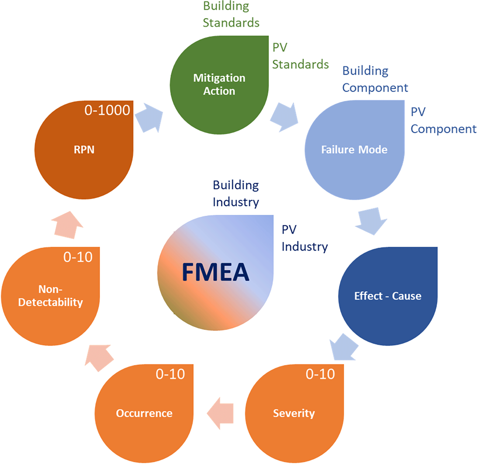
Figure 4. Workflow for Failure Mode and Effects Analysis (FMEA).
Certification paths for the MC2.0 products
Building cladding end-products with integrated PV
In this section, certification strategies for building cladding products integrating flexible PV modules (SFs) are addressed, focusing on aluminium façades and polymer roof tiles. Both products fall under BIPV applications, where the SF is a flexible PV module attached to the cladding. For the examples investigated here, it is assumed that the junction box is mounted on the PV module. An FMEA was conducted at three levels: SF, cladding, and their interface, to identify failure modes with the highest RPN.
Most SF-related risks are covered by IEC 6173018,19 and IEC 61215.20,21 IEC 61730 is prioritised as it addresses safety, while IEC 61215 focuses on reliability. The full IEC 61730 standard can be applied at the SF level, except for the mechanical load test, which should be conducted at the IPV level, and the module breakage test, which is not applicable. Consequently, Sequence D from IEC 61730 should be removed from SF testing and applied at the IPV level. Likewise, the hot-spot endurance test is unsuitable for SFs since it requires the complete IPV product, due to different thermal properties after integration. Therefore, Sequence F from IEC 61730 should also be shifted to the IPV level. Reliability certification per IEC 61215 is meaningful only at the full product level, considering attachment type and mechanical integration. Certification can be performed by the PV module manufacturer (on representative samples for targeted markets) or by the end-product manufacturer if the SF is not pre-certified.
Aluminium façade case
The SF is adhesively bonded to aluminium cassettes. In addition to IEC standards, compliance with DIN 18516–145 for claddings is mandatory, requiring structural calculations for various load transfers (dead, wind, snow, seismic), static testing for joints and material durability against moisture, temperature, and UV. Wind load resistance follows DIN EN 1991–1-4.48 Fire safety requires DIN EN 13501–130 classification (A2-s1-d0), necessitating interface-level fire testing due to polymer components. Corrosion protection must meet DIN EN ISO 12944.52,53 Recommended interface tests include peel tests combined with humidity-freeze (HF) and damp-heat (DH) ageing, hail impact, and electrical integrity checks, such as I-V and electroluminescence (EL) measurements (
Figure 5). It must be noted that the standards were selected according to the region of interest for this product, which is Switzerland.
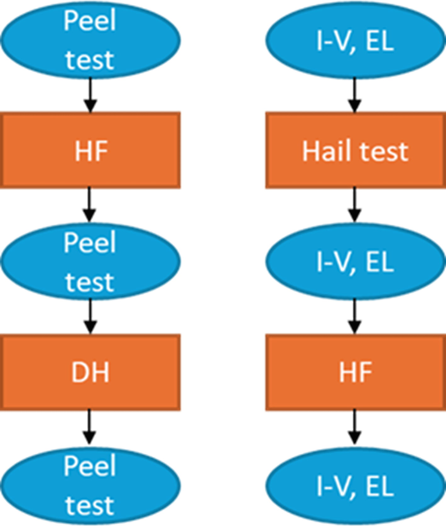
Figure 5. Testing suggestion for the attachment of the Semi-Fabricate (SF) to the cassette, where HF is Humidity Freeze and DH is Damp Heat.
Polymer roof tile case
Here, the SF is mechanically fixed to injection-moulded polymer tiles using integrated clips for easy dismantling. FMEA identified attachment reliability as critical. Certification follows NEN 725054 (requirements for construction elements with PV functionality), which mentions norms for airtightness (NEN 268655), moisture proofing (NEN 277856), noise protection (NEN 507757), fire safety (NEN 606358), attachment methods (NEN 670746 and NEN 670847), assessment of structural safety in case of renovation (NEN 870059), energy performance (NTA 880060), basis of constructive design (NEN-EN 1990 + A161), snow-, wind- and thermal loads (NEN-EN 1991–1-3,62 1991–1-4,48 1991–1-563), uplift resistance of (clay or concrete) rooftiles (NEN-14437:200464) and lightning protection (NEN-EN-IEC 6230565). Additional tests are advised for vibration risk under wind loads (e.g., wind tunnel testing) and hotspot formation under high-temperature operation, especially near cabling. It must be noted that the standards were selected according to the region of interest for this product, which is The Netherlands.
IGU BIPV end-products
In this product family, end-products must comply not only with PV-related IEC standards, but also with EN 1279 (Glass in Buildings: Insulated Glass Units).35–38 The certification approach, based on the FMEA conducted, aims to identify which tests can only be carried out at the end-product level, minimising redundant testing at both SF and end-product levels. Tests at the SF level primarily focus on electrical properties and safety, while end-product tests focus on the integrity and safety of the full IGU assembly, considering structural, thermal, moisture, and long-term reliability when PV elements are integrated within IGUs.
Tests applicable exclusively at the end-product level are summarised in
Table 3. These evaluate not only PV performance but also interactions between the SF, glass configuration, edge seal system, and mounting conditions (e.g., fixed SF or integration within venetian blinds).
Table 3. Tests applicable exclusively at the Insulated Glazing Unit (IGU) Building Integrated Photovoltaic (BIPV) end-product level.
| PV related tests |
IGU related tests |
|---|
| Thermal cycling | Climate sequence test |
| Humidity freeze | Gas leakage rate |
| Damp heat | Physical attributes |
| UV test | U-value measurement |
| Mechanical load test | Solar factor and transmittance |
| Hail test | Glass structural requirements |
| Fire test | |
| Ignitability test | |
| Module breakage test | |
Considering the SFs and their certification with IEC 61730,18,19 similarly to the building claddings, it is recommended to perform Sequence D and Sequence F only at the end-product level. These sequences are not relevant at SF level because conditions (e.g., thermal, mechanical) differ significantly when the SFs are integrated into the IGUs, and Sequence F applies only after the final electrical connections are added.
Conclusions
This article addresses the distinctive challenges of Integrated Photovoltaic (IPV) certification that stem from wide variation in designs, integration contexts, and regulatory landscapes. Existing certification schemes built around standardised PV modules and high-volume product lines are not consistent with a larger deployment of mass-customised solutions or intermediate components. Semi-fabricates (SFs) are, by definition, incomplete; they may omit junction boxes, mechanical supports, or other critical elements, making full PV certification premature. At the other end, imposing full PV certification on niche IPV end-products can threaten bankability, particularly when construction codes and PV standards overlap, leading to duplicative testing.
To bridge this gap, we propose a stepwise workflow. It starts with a comprehensive review of product requirements, applicable standards, and national regulations, and proceeds with Failure Mode and Effects Analysis (FMEA) at the SF-, product-, and interface-level. This allows to select norms and, where appropriate create tailored test sequences. This targeted approach avoids redundant retesting while preserving safety and reliability.
To further streamline IPV certification, we advocate for harmonised guidance that aligns PV standards, Building Integrated Photovoltaic (BIPV) provisions, and construction regulations within a single framework. Close coordination with standardisation bodies and insurers is essential to keep safety a central element without imposing undue costs on manufacturers. Priority should be given to defining representative attachment scenarios for SFs so that meaningful certification can occur at the sub-assembly level when appropriate. In parallel, modular, family-based test sequences, rather than per design qualification, can materially reduce time and cost. Ongoing engagement with product owners, insurers, and authorities will be pivotal to adapting this framework and accelerating the uptake of innovative BIPV across various applications.
Achieving consistent IPV certification across Europe will require decisive steps at the EU level. The European Commission must issue Standardisation Requests (SReqs) to CEN defining what constitutes BIPV, which characteristics are essential, and what the future harmonised European Standard (hEN) must include. A clear deadline for development of the hEN, followed by its publication and listing in the Official Journal of the EU, will allow CE marking to begin under CPR 2024. Only then will Member States be required to remove national barriers that currently hinder BIPV market entry. Addressing these structural gaps is critical: current certification practices impede the deployment of PV within the building envelope. Legislative and standardisation progress will not only streamline BIPV integration across Europe but will also support the European Commission’s broader goal of revitalising PV manufacturing within the EU through safer, more coherent market access pathways.
Use of AI
The tool M365 Copilot, powered by the GPT-5–based chat model (provided by the host institution of the corresponding author), has been used to improve the writing style and the flow of the text. Moreover, it has been used for the description of some of the norms, which were then double-checked by the authors.
Ethics and consent
Ethical approval and consent were not required.
Disclaimer
The views expressed in this article are those of the author(s). Publication in Open Research Europe does not imply endorsement of the European Commission.







