Introduction
SOCRATCES is an EU-funded project investigating the feasibility of calcium-looping in renewable energy storage1. The core concept includes capturing solar energy by its application in breaking down CaCO3 into CaO and CO2, followed by an exothermic reunification of the products to regenerate CaCO32. The heat liberated in the second of these two steps in a reactor named carbonator3 is then utilized to drive a power cycle. Calcium-looping itself is a proven technology4, with the carbonation and calcination reactor design being at the center of focus5.
In the pilot 10 kWth capacity installation of SOCRATCES in Seville, Spain, a small Stirling engine was considered for integration. The engine was a 1 kWe free-piston β Stirling machine manufactured by Microgen Engine Corporation6. To the best of the authors’ knowledge, it is the first instance of such a combination, that of a Stirling engine with an exothermic reactor. Barring solar applications, Stirling engines are commonly deployed with a burner in which a fuel is consumed to provide the required thermal power7, the dominant non-combustion application being that of power generation from waste heat8,9. Therefore, the idea of combining a Stirling engine with the exothermic reactor is unique. While many different power cycles were considered for implementation10, the Stirling cycle was chosen for SOCRATCES for its novelty and uniqueness.
Experimental setup
As the deployment involved no combustion, it was essential to modify the engine’s external construction to facilitate integration. The engine’s heater is a dome with radially protruding rows of fins. It was decided, after extensive computational fluid dynamic analysis of the heat transfer, that it would be most feasible to feed the hot air received from the carbonator in an opposed-blast configuration, which involves bifurcating the flow and introducing it to the engine’s heater in two centrally-opposite feeders.
The process and instrumentation diagram of the experimental setup has been presented in Figure 1. The Stirling engine receives hot air carrying the heat liberated during the exothermic reaction in the carbonator and absorbs a fraction of the available energy. The “exhaust” is then passed on to a heat exchanger which preheats the input of fresh air to the carbonator. It has to be noted that the cycle is ideally expected to be closed; however, for economic and technical conveniences, given that it was an experimental pilot scale plant, it was kept open. A small pump circulated a cooling fluid (water) to cool the cold side of the engine, the heat finally being rejected to the atmosphere with the aid of a fan-powered radiator. Temperatures, pressures and flow rates are measured at the points shown in the P&ID. A three-dimensional CAD model of the setup has been shown in Figure 2.
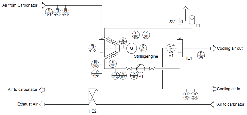
Figure 1. P&ID of the experimental setup.
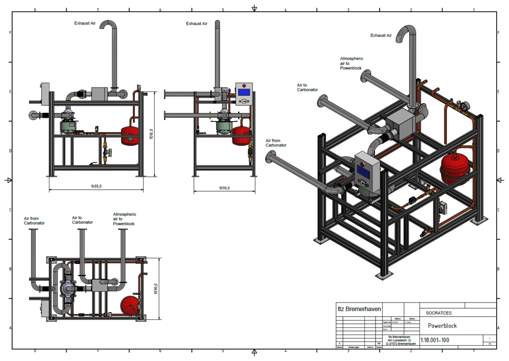
Figure 2. SOCRATCES power block CAD model showing components and connections (uninsulated).
The engine was tested using two high temperature electric heaters to simulate the carbonator. Two blowers were used to force atmospheric air through the heaters at variable flowrates. The temperature were controlled separately using controllers. Thus, it was possible to achieve virtually any combination, within a particular range, of temperature and flowrate to be fed to the Stirling engine. It has to be mentioned here that the feeder and the enclosure were heavily insulated to minimize heat loss. Figure 3 shows the power block in its late stage of construction with the Stirling engine mounted on a frame. The Stirling engine’s bifurcating inlet can be seen. The plate heat exchanger is on top of the frame connected to the enclosure outlet. In Figure 4, the heaters deployed in initial tests without insulation can be seen. The container houses the engine along with the controls. The structure outside has the blowers and heaters mounted on it. The blower seen here is sending air to the heat exchanger to be preheated. The radiator can be seen on top of the container.
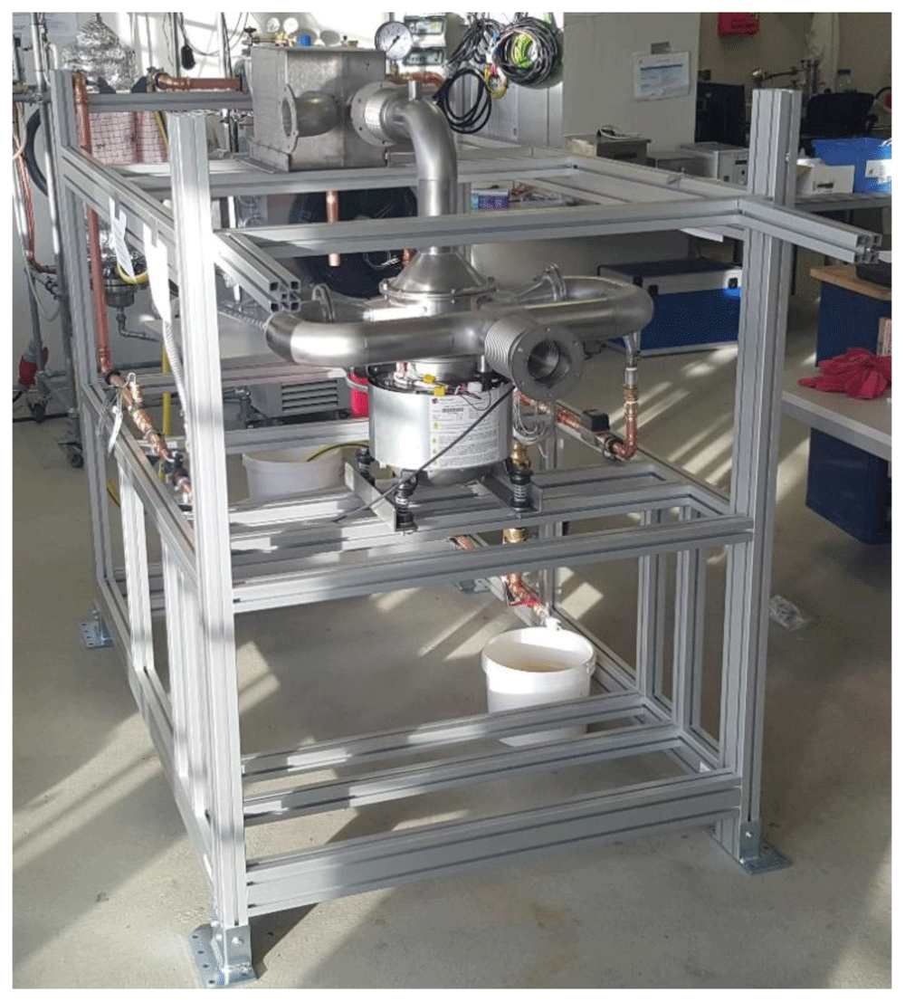
Figure 3. Power block in its late stage of construction.
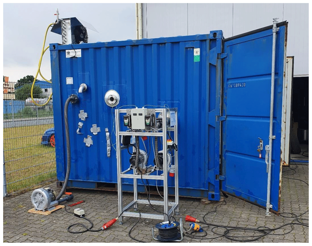
Figure 4. Heaters deployed in testing the engine.
The installed recuperator was a Bosal® (Vianin, the Netherlands) P5 thin-walled heat exchanger able to operate at an effectiveness of about 80–90% within the range of flow specified by the carbonator11. It has a welded and compact plate modular design. A 6.46 kW axial fan-powered Anthermo® (Kamen, Germany) radiator was used to cool the cold side of the engine. The cooling pump was a Wilo-Yonos® model able to generate a maximum flowrate of 13 l/min. Both the radiator fan and the pump had speed control functions to allow variation of flowrates. The heaters used were Herz® (Neuwied, Germany) XL92HT (15 kW, 400 VAC). They were fed with air using high-pressure Herz® (Neuwied, Germany) blowers (HD 140).
Methods
The engine was fed with flowrates at temperatures expected to be encountered from the carbonator. It was noticed that it took about a quarter of an hour for the system to stabilize at any combination of temperature and flowrate. These combinations were achieved using the controllers on the heaters (temperatures) and blowers (flowrates). When the steady-state was attained, all the temperatures, pressures, flowrates and the power produced by the Stirling engine was recorded using the installed sensors shown in the P&ID (Figure 1). When the temperature and the flowrate, either separately or together, were altered, the engine responded with a shift in its power production. The electric power climbed with time until the rate of increase became negligible, indicating steady-state.
Several Key Performance Indicators (KPIs) were considered in the evaluation of the performance of the system. These are described below.
KPI-1 Power production
The electricity produced is directly read from the wattmeter mounted on the control box that accompanies the engine.
KPI-2 Energy provided to the enclosure
The difference in enthalpy between the inlet and the outlet indicates how efficiently heat is absorbed by the Stirling engine. It indicates the heat flux in the direction of the engine core.
KPI-3 Logarithmic mean temperature difference (LMTD)
The heat recovery efficiency of the recuperator is indicated by the LMTD of the heat exchanger.
KPI-4 Heat lost
Efficiency of the preheating process in the integration scheme is reflected in the heat lost. The fluid in this case is air.
KPI-5 Heat rejected
The cooling performance of the Stirling engine is measured by the amount of heat rejected to the atmosphere. The fluid in this case is water.
KPI-6 Conversion efficiency
Knowing the power produced and the enthalpy difference across the Stirling engine, the conversion efficiency can be computed by dividing the former by the latter.
Results and discussion
The parameters studied are identified in Table 1. Collected experimental data and the derived variables are tabulated in Table 2 and Table 3.
Table 1. Variables and parameters.
| Ta | Ambient temperature |
| min | Hot air flowrate to the engine |
| Tin | Temperature of the hot air to the engine |
| Tout | Temperature of the hot air exiting the engine |
| Thead | Engine head temperature |
| mw | Cooling water mass flowrate |
| Tw,in | Temperature of incoming cooling water |
| Tw,out | Temperature of outgoing cooling water |
| mc | Carbonator blower flowrate |
| Tc,in | Temperature of air delivered to the carbonator |
| Tr | Temperature of rejected hot air |
| P | Power |
| CFS | Cooling fan speed |
| KPI1 | Power |
| KPI2 | Enclosure energy |
| KPI3 | Log mean temperature difference of the heat exchanger |
| KPI4 | Heat lost |
| KPI5 | Heat rejected |
| KPI6 | Conversion efficiency |
Table 2. Measured experimental data.
| No. | Ta (°C) | min (kg/s) | Tin (°C) | Thead (°C) | Tout (°C) | mw (l/min) | Tw,in (°C) | Tw,out (°C) | mc (kg/s) | Tc,in (°C) | Tr (°C) | CFS (RPM) |
|---|
| 1 | 17 | 0.013 | 470 | 250 | 358 | 13 | 32.2 | 33.6 | 0.0345 | 136 | 31 | 1200 |
| 2 | 17 | 0.013 | 470 | 250 | 358 | 13 | 32.2 | 33.6 | 0.0121 | 242 | 49 | 1200 |
| 3 | 17 | 0.013 | 530 | 298 | 399 | 13 | 33 | 34.5 | 0.0345 | 155 | 39 | 1200 |
| 4 | 17 | 0.013 | 530 | 298 | 399 | 13 | 33 | 34.5 | 0.0121 | 279 | 83 | 1200 |
| 5 | 17 | 0.013 | 603 | 350 | 438 | 13 | 33 | 34.9 | 0.0121 | 329 | 102 | 1200 |
| 6 | 17 | 0.013 | 603 | 350 | 438 | 13 | 33 | 34.9 | 0.0345 | 199 | 56 | 1200 |
| 7 | 17 | 0.0163 | 351 | 199 | 267 | 13 | 30 | 31.3 | 0.0345 | 122 | 34 | 1200 |
| 8 | 17 | 0.0163 | 351 | 199 | 267 | 13 | 30 | 31.3 | 0.0121 | 218 | 49 | 1200 |
| 9 | 17 | 0.0163 | 437 | 254 | 335 | 13 | 30 | 31.5 | 0.0121 | 291 | 53 | 1200 |
| 10 | 17 | 0.0163 | 437 | 254 | 335 | 13 | 30 | 31.5 | 0.0345 | 161 | 31 | 1200 |
| 11 | 17 | 0.0163 | 522 | 316 | 400 | 13 | 32 | 34.0 | 0.0345 | 155 | 31 | 1200 |
| 12 | 17 | 0.0163 | 522 | 316 | 400 | 13 | 32 | 34.0 | 0.0121 | 335 | 150 | 1200 |
| 13 | 13 | 0.026 | 519 | 358 | 416 | 13 | 26.9 | 29.2 | 0.0345 | 245 | 43 | 1200 |
| 19 | 13 | 0.0326 | 363 | 246 | 311 | 13 | 18.7 | 20.8 | 0.0121 | 281 | 153 | 1200 |
| 20 | 13 | 0.0326 | 363 | 246 | 311 | 13 | 18.7 | 20.2 | 0.0345 | 235.6 | 63 | 1200 |
| 21 | 13 | 0.0326 | 465 | 325 | 403 | 13 | 24.6 | 26.2 | 0.0345 | 283.8 | 63 | 1200 |
| 22 | 13 | 0.0326 | 465 | 325 | 403 | 13 | 24.6 | 26.2 | 0.0121 | 371.5 | 224 | 1200 |
| 23 | 13 | 0.0326 | 556 | 393 | 478 | 13 | 26.6 | 28.7 | 0.0121 | 436.4 | 266 | 1200 |
| 24 | 13 | 0.0326 | 556 | 393 | 478 | 13 | 26.6 | 28.7 | 0.0345 | 351.6 | 90 | 1200 |
Table 3. "Key Performance Indicators".
| No. | KPI1 (W) | KPI2 (kW) | KPI3 (N/A) | KPI4 (kW) | KPI5 (kW) | KPI6 (%) |
|---|
| 1 | 173 | 1.49 | 205.77 | 2.94 | 1.26 | 11.65 |
| 2 | 173 | 1.49 | 264.78 | 1.54 | 1.26 | 11.65 |
| 3 | 310 | 1.74 | 231.53 | 3.24 | 1.40 | 17.85 |
| 4 | 310 | 1.74 | 288.16 | 1.59 | 1.40 | 17.85 |
| 5 | 448 | 2.19 | 323.85 | 1.45 | 1.69 | 20.48 |
| 6 | 448 | 2.19 | 269.75 | 3.17 | 1.69 | 20.48 |
| 7 | 15 | 1.40 | 160.59 | 2.41 | 1.21 | 1.07 |
| 8 | 15 | 1.40 | 209.38 | 0.81 | 1.21 | 1.07 |
| 9 | 190 | 1.70 | 277.98 | 0.73 | 1.33 | 11.20 |
| 10 | 190 | 1.70 | 214.13 | 2.89 | 1.33 | 11.20 |
| 11 | 365 | 2.03 | 234.87 | 4.07 | 1.78 | 17.99 |
| 12 | 365 | 2.03 | 282.64 | 1.08 | 1.78 | 17.99 |
| 13 | 510 | 2.73 | 296.94 | 4.53 | 2.10 | 18.67 |
| 19 | 221 | 1.73 | 208.18 | 1.00 | 1.90 | 12.78 |
| 20 | 221 | 1.73 | 235.07 | 2.51 | 1.40 | 12.78 |
| 21 | 425 | 2.06 | 304.09 | 3.96 | 1.45 | 20.61 |
| 22 | 425 | 2.06 | 258.44 | 1.05 | 1.45 | 20.61 |
| 23 | 636 | 2.59 | 305.61 | 1.38 | 1.87 | 24.52 |
| 24 | 636 | 2.59 | 362.74 | 4.20 | 1.87 | 24.52 |
The Stirling engine’s power was found to be a linear function of the temperature of the head of the Stirling engine (Figure 5). This is consistent with the characteristics reported by the manufacturer. The engine begins to move at a temperature of approximately 180 °C, the minimum head temperature for electricity generation. The electric power and the head temperature are related by the following empirical relationship:
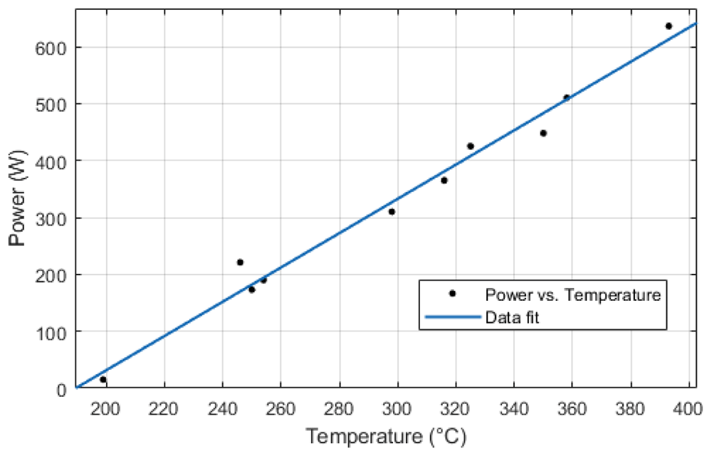
Figure 5. Power versus head temperature plot.
The head temperature can be empirically related, using a logistic function, for the sake of operational convenience of the carbonator or any other heat source, to the temperature and the flowrate of the incoming heating fluid.
A surface plot of this relationship is given in Figure 6.
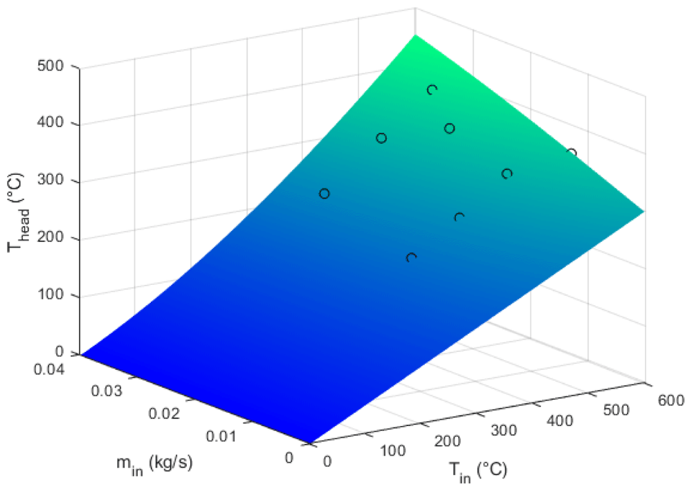
Figure 6. The head temperature as a function of the mass flowrate and the incoming temperature.
Combining Equation 5 and Equation 6, we get
This expression will be useful in the integration of the power block with the carbonator as it will be possible to estimate the power output as a function of the flowrate and the temperature using a simplistic relationship. While extrapolation beyond the recommended range is possible, some inaccuracy should not be unexpected. It is also important to mention that as the system takes a while to reach the steady-state, some inaccuracy is in the model is unavoidable.
Coolant rate variations’ impact on power production was tested. The system’s response was an increase in the coolant temperature without a significant impact on the electrical power. The power fell only slightly when the flowrates was below 10 l/min.
Perhaps the most interesting observation apparent in these tests is that the Stirling engine has an attractive thermal to electricity conversion efficiency (25%). While it would have been ideal had it been able to absorb more thermal power, it is noted that the installation of a downstream heat exchanger alleviates the difficulty considerably. The heat exchanger is able to send out significantly preheated air to the reactor. This is obvious from the data collected in the 23rd test (Table 2) where it is seen that the heat exchanger, one with a very high effectiveness, is sending out preheated air at 436 °C to the carbonator. This heat, of course, can be used as process heat for industrial applications as well. It can be thus said that this implementation is remarkably efficient. One also has to take note that this efficiency is achieved at a comparatively much lower working fluid temperature. Even though internal temperatures were not measured in this test, it is clear that they would be much lower than the heating fluid’s temperature. For example, in the 23rd recorded test, a heating fluid temperature of 556 °C was able to reach an efficiency of near 25%. Since about 2.59 kW of heat was injected into the interior, it is clear that a substantial temperature difference existed between the heating and the working fluids.
Since the SOCRATCES concept is environmentally completely safe, its combination with the Stirling cycle, the latter being emission free, is thus revealed to be extremely interesting, warranting future investigations. While the study reported in this paper used a pair of heaters to assess the feasibility of integration with the carbonator, it would be interesting to study the engine’s response as a function of the reactor parameters, such as reactant flowrate, temperature and pressure. In addition, optimization of the design of the engine core to enhance compatibility with the exothermic reactor can also be of great interest.
Data availability
Underlying data
All data underlying the results are available as part of the article and no additional source data are required.