1. Introduction
Within the scope of the seismic response of reinforced concrete structures, the goal of this project is to study the response of flat slab floors with drop panels at a large scale (representative of real structures), made with concrete with coarse recycled concrete aggregate (CRCAC), under combined gravity and lateral loads. The research integrates environmental sustainability, structural safety and innovative testing methodologies. It represents the first worldwide experimental campaign targeting pseudo-dynamic and cyclic behaviour of CRCAC flat slabs, providing insights into punching shear performance, damage progression and overall seismic resilience of sustainable multi-storey concrete buildings.
Testing a drop panel solution is aligned with the UN’s sustainable development goals,1 particularly for the reduction of material consumption and the associated CO2-eq production. In the last decades, the dominant structural typology with respect to buildings and parking garages has been flat slabs. Despite its architectural advantages due to a flat soffit, the material consumption of this type of structure is highly inefficient and is thus associated to a non-justified environmental impact.2 With the drop panel solution, the slab’s thickness is higher at the slab-column connections, using more material where it is needed the most, increasing the structural efficiency.
Construction and demolition waste (CDW) accounts for over 40% of the waste produced in the European Union (EU27) and the sector of aggregates for construction is the world’s largest non-energy extractive sector worldwide. Therefore, recovering CDW as recycled aggregates for concrete is a sustainable option for the construction sector, in full compliance with the European Union’s Circular Economy Action Plan.3 The potential benefits of such recovery are significant since concrete is the world’s most used material after water. However, in most regions, recycled aggregates are mostly downcycled in landfilling and backfilling operations. The material behaviour of concrete made with coarse recycled concrete aggregates (CRCAC) is well understood by the scientific community, as well as its most common resistance mechanisms and it is found that CRCAC is a suitable structural material. Yet, in most regions, CRCAC is not produced.
This occurs because of scepticism about CRCAC applications from clients, contractors and designers, partly due to the lack of large-scale demonstrations of CRCAC’s structural viability and the absence of tests for specific types of structural elements, which prevent the existence of clear design guidelines covering all relevant resistance mechanisms and types of structural elements.
This is the case of flat slabs, a common and resource-efficient structural solution. Slabs typically constitute a significant portion of the total concrete volume used in a building and therefore represent a promising application for structural CRCAC. However, there are few studies on the punching behaviour of flat slabs made with CRCAC under gravity loading, hindering the practical use of CRCAC. Furthermore, no studies have yet investigated the seismic behaviour of CRCAC flat slabs, which is a subject of special importance in moderate to intense seismic areas. Unsatisfactory knowledge about the behaviour of CRCAC flat slabs under gravity loading and, especially, seismic actions, together with the absence of large-scale demonstration projects are obstacles to a larger use of CRCAC, justifying the need for research on this subject.4
The seismic response of flat slab systems can be satisfactory when combined with a primary wall or frame system, which limits P-delta effects and reduces damage to non-structural infills.5 In Europe, however, seismic design provisions for flat slab structures are still being developed,5 with new provisions currently being introduced in the draft version of Eurocode 8. Application to these in the design of a large-scale experimental specimen represents an important verification. Another relevant aspect concerns the detailing of slab–column connections at corner and edge columns. Previous experimental studies showed the importance of these regions,6–8 while seismic design rules and European code specifications are still required.
From this project, several papers were produced, where further information can be obtained.9–12 Several tests on isolated slab column connections using CRCAC were also made by members of this research team, serving as support information for this project.13–15
2. Experimental campaign
2.1 Test specimen
The two-storey test structure features CRCAC flat slabs, arranged in a three-by-two bay layout. The spans in the longitudinal direction measured 4.5 m and 5.0 m, while all transverse spans were 4.5 m. Each storey had a height of 3.2 m. The slabs incorporate drop panels with a thickness of 0.25 m, with the rest of slab being 0.15 m thick (Figs. 1 and 2).
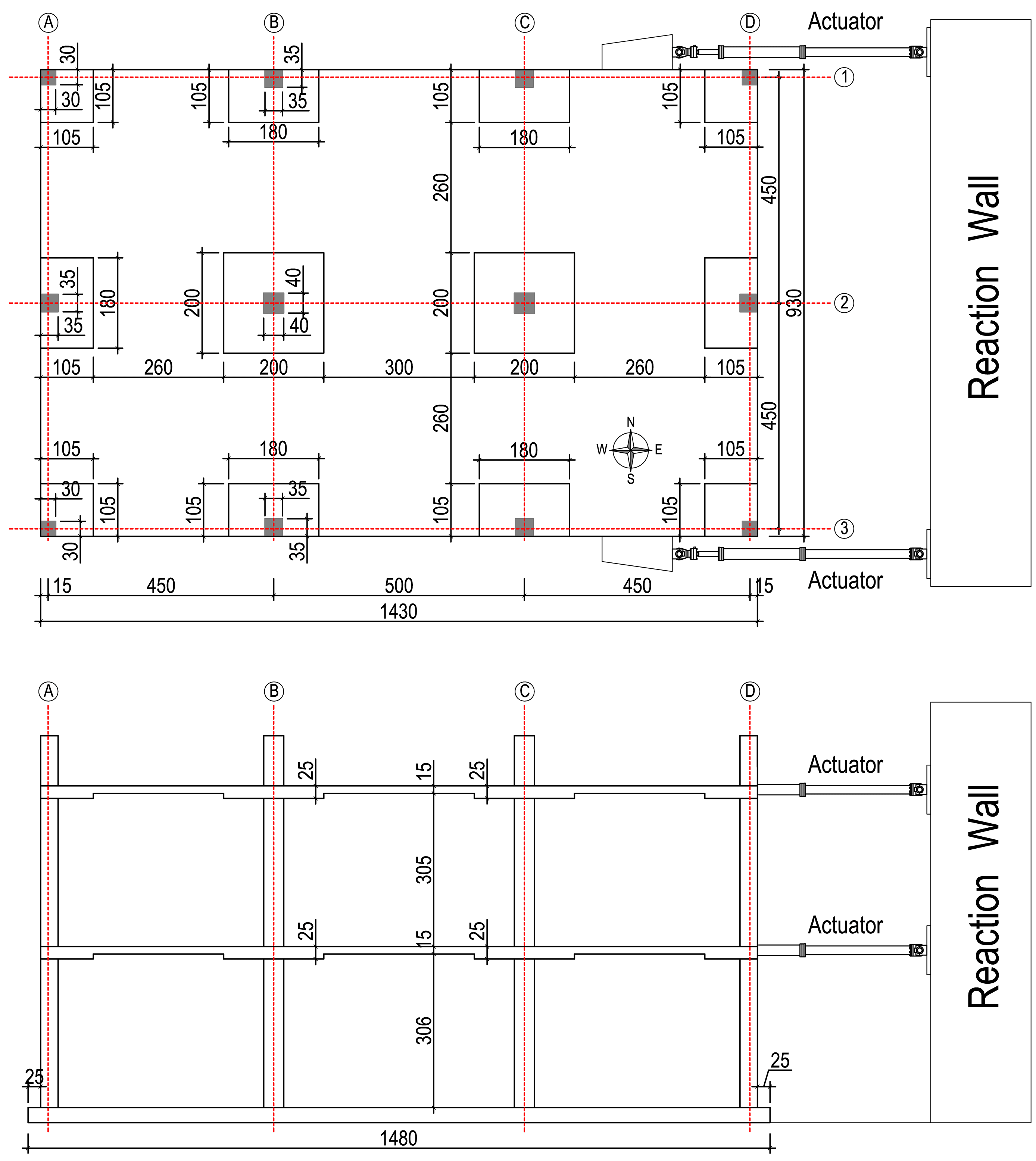
Figure 1. Building geometry (dimensions in cm).
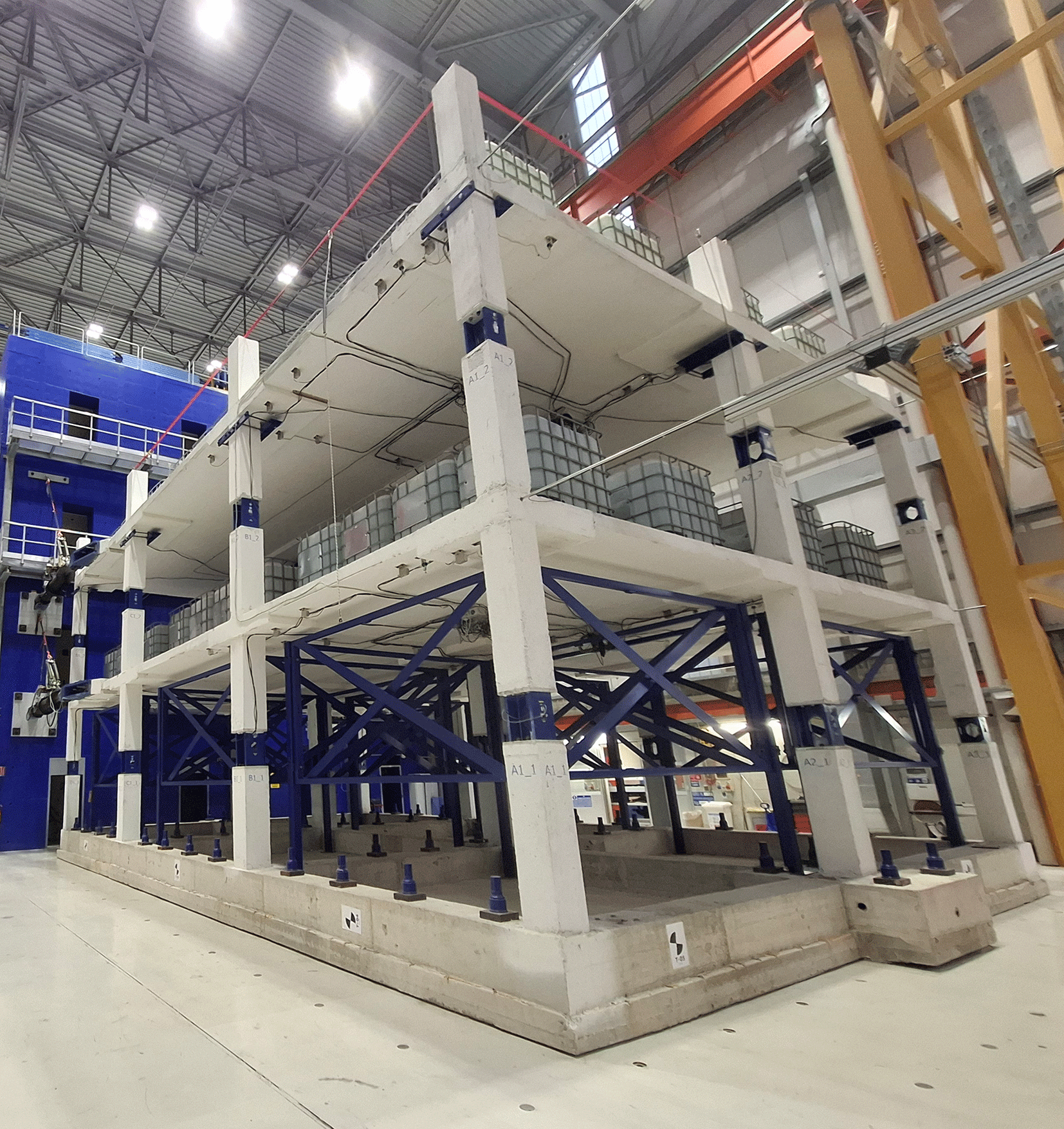
Figure 2. Building inside the laboratory during testing.
The square column cross-sections vary by location, with a side dimension equal to: 0.40 m for interior columns, 0.35 m for edge columns and 0.30 m for corner columns. Steel load cells were embedded at mid-height of the columns during construction to record internal force demands, following experimental practices previously used at the JRC ELSA laboratory.6–8
The structure rests on a reinforced concrete beam-grid foundation designed for repositioning within the lab and for firm anchorage to the strong floor. The size of the JRC ELSA reaction wall accommodates testing of this two-storey flat-slab building, which measures 6.4 m in height, 14.3 m in length, and 9.3 m in width.
The building was designed for a dead load corresponding to the self-weight of the structural elements plus an allowance for the self-weight of non-structural elements of 3 kN/m2. The live load was taken as 2 kN/m2, assuming ψ2 = 0.30 (for assessment of the quasi-permanent loading). The design earthquake action consisted of a 0.6% horizontal drift ratio. The longitudinal reinforcement detailing in both slabs was the same, although the first-floor slab contained shear studs as punching shear reinforcement. For the second-floor slab that initially did not contain punching shear reinforcement, provisions were made for retrofitting half of the connections using post-installed shear reinforcement. Such installation took place after the first phase of the experimental campaign, and it is traced by the specimen configuration switching from As-built to Retrofitted (see also
Table 6).
Table 1. Recycled aggregate concrete composition.
| Cement (kg/m3) | Water (l/m3) | Sand 0/8 (kg/m3) | Recycled concrete aggregate 8/16 (kg/m3) | Plasticizer (l/m3) |
|---|
| 380 | 190 | 1061 | 689 | 3.8 |
Table 2. Compressive concrete strength.
| Age (days) | 28 | 56 |
222–265 |
|---|
| fcm,cube (MPa) | 39.2 | 42.4 | 52.1 |
Table 3. List of actuator sensors.
| Label | Sensor | Capacity | Actuator Label | Location |
Slab |
|---|
| TEMPO_1 | Temposonic | 1000 mm | Con1 | North-East corner | 1 |
| HEIDE_1 | Heidenhaim | 1000 mm | North-East corner |
| LC_1 | Load cell | ±1000 kN | North-West corner |
| TEMPO_2 | Temposonic | 1000 mm | Con2 | South-East corner | 1 |
| HEIDE_2 | Heidenhaim | 1000 mm | South -East corner |
| LC_2 | Load cell | ±1000 kN | South -West corner |
| TEMPO_3 | Temposonic | 1000 mm | Con3 | North-East corner | 2 |
| HEIDE_3 | Heidenhaim | 1000 mm | North-East corner |
| LC_3 | Load cell | ±1000 kN | North-West corner |
| TEMPO_4 | Temposonic | 1000 mm | Con4 | South-East corner | 2 |
| HEIDE_4 | Heidenhaim | 1000 mm | South -East corner |
| LC_4 | Load cell | ±1000 kN | South -West corner |
Table 4. List of sensors on columns and slab.
| Label | Sensor type | Capacity | Column | Side/End | Floor/Slab |
|---|
| C_IN_F1_A1_T
| Inclinometer | ±5° | A1 | Top | 1 |
| C_IN_F1_A1_B
| Inclinometer | ±5° | A1 | Base | 1 |
| C_IN_F1_A2_T
| Inclinometer | ±5° | A2 | Top | 1 |
| C_IN_F1_A2_B
| Inclinometer | ±5° | A2 | Base | 1 |
| C_IN_F1_B2_T
| Inclinometer | ±5° | A2 | Top | 1 |
| S_IN_F1_A1_E1
| Inclinometer | ±5° | A1 | East (close to column) | 1 |
| S_IN_F1_A1_E2
| Inclinometer | ±5° | A1 | East (far from column) | 1 |
| S_IN_F1_B1_W1
| Inclinometer | ±5° | B1 | West (close to column) | 1 |
| S_IN_F1_B1_W2
| Inclinometer | ±5° | B1 | West (far from column) | 1 |
| S_IN_F1_B1_E1
| Inclinometer | ±5° | B1 | East (close to column) | 1 |
| S_IN_F1_B1_E2
| Inclinometer | ±5° | B1 | East (far from column) | 1 |
| S_IN_F1_B1_S1
| Inclinometer | ±5° | B1 | South (close to column) | 1 |
| S_IN_F1_B1_S2
| Inclinometer | ±5° | B1 | South (far from column) | 1 |
| S_IN_F1_A2_E1
| Inclinometer | ±5° | A2 | East (close to column) | 1 |
| S_IN_F1_A2_E2
| Inclinometer | ±5° | A2 | East (far from column) | 1 |
| S_IN_F1_B2_W1
| Inclinometer | ±5° | B2 | West (close to column) | 1 |
| S_IN_F1_B2_W2
| Inclinometer | ±5° | B2 | West (far from column) | 1 |
| S_IN_F1_B2_E1
| Inclinometer | ±5° | B2 | East (close to column) | 1 |
| S_IN_F1_B2_E2
| Inclinometer | ±5° | B2 | East (far from column) | 1 |
| S_IN_F1_B2_N1
| Inclinometer | ±5° | B2 | North (close to column) | 1 |
| S_IN_F1_B2_N2
| Inclinometer | ±5° | B2 | North (far from column) | 1 |
| POT_F1_A1_E1
| Potentiometer | 25 mm | A1 | East (close to column) | 1 |
| POT_F1_A1_E2
| Potentiometer | 25 mm | A1 | East (far from column) | 1 |
| POT_F1_A2_E1
| Potentiometer | 25 mm | A2 | East (close to column) | 1 |
| POT_F1_A2_E2
| Potentiometer | 25 mm | A2 | East (far from column) | 1 |
| POT_F1_B2_W1
| Potentiometer | 25 mm | B2 | West (close to column) | 1 |
| POT_F1_B2_W2
| Potentiometer | 25 mm | B2 | West (far from column) | 1 |
| POT_F1_B2_E1
| Potentiometer | 25 mm | B2 | East (close to column) | 1 |
| POT_F1_B2_E2
| Potentiometer | 25 mm | B2 | East (far from column) | 1 |
| C_IN_F1_C2_T
| Inclinometer | ±5° | C2 | Top | 1 |
| C_IN_F1_D2_T
| Inclinometer | ±5° | D2 | Top | 1 |
| C_IN_F1_D3_T
| Inclinometer | ±5° | D3 | Top | 1 |
| C_IN_F2_A1_T
| Inclinometer | ±5° | A1 | Top | 2 |
| C_IN_F2_A1_B
| Inclinometer | ±5° | A1 | Base | 2 |
| C_IN_F2_A2_T
| Inclinometer | ±5° | A2 | Top | 2 |
| C_IN_F2_A2_B
| Inclinometer | ±5° | A2 | Base | 2 |
| C_IN_F2_B2_T
| Inclinometer | ±5° | B2 | Top | 2 |
| C_IN_F2_B2_B
| Inclinometer | ±5° | B2 | Base | 2 |
| S_IN_F2_A1_E1
| Inclinometer | ±5° | A1 | East (close to column) | 2 |
| S_IN_F2_A1_E2
| Inclinometer | ±5° | A1 | East (far from column) | 2 |
| S_IN_F2_B1_W1
| Inclinometer | ±5° | B1 | West (close to column) | 2 |
| S_IN_F2_B1_W2
| Inclinometer | ±5° | B1 | West (far from column) | 2 |
| S_IN_F2_B1_E1
| Inclinometer | ±5° | B1 | East (close to column) | 2 |
| S_IN_F2_B1_E2
| Inclinometer | ±5° | B1 | East (far from column) | 2 |
| S_IN_F2_B1_S1
| Inclinometer | ±5° | B1 | South (close to column) | 2 |
| S_IN_F2_B1_S2
| Inclinometer | ±5° | B1 | South (far from column) | 2 |
| S_IN_F2_A2_E1
| Inclinometer | ±5° | A2 | East (close to column) | 2 |
| S_IN_F2_A2_E2
| Inclinometer | ±5° | A2 | East (far from column) | 2 |
| S_IN_F2_B2_W1
| Inclinometer | ±5° | B2 | West (close to column) | 2 |
| S_IN_F2_B2_W2
| Inclinometer | ±5° | B2 | West (far from column) | 2 |
| S_IN_F2_B2_E1
| Inclinometer | ±5° | B2 | East (close to column) | 2 |
| S_IN_F2_B2_E2
| Inclinometer | ±5° | B2 | East (far from column) | 2 |
| S_IN_F2_B2_N1
| Inclinometer | ±5° | B2 | North (close to column) | 2 |
| S_IN_F2_B2_N2
| Inclinometer | ±5° | B2 | North (far from column) | 2 |
| POT_F2_A1_E1
| Potentiometer | 25 mm | A1 | East (close to column) | 2 |
| POT_F2_A1_E2
| Potentiometer | 25 mm | A1 | East (far from column) | 2 |
| POT_F2_A1_S1
| Potentiometer | 25 mm | A1 | South (close to column) | 2 |
| POT_F2_A1_S2
| Potentiometer | 25 mm | A1 | South (far from column) | 2 |
| POT_F2_A2_E1
| Potentiometer | 25 mm | A2 | East (close to column) | 2 |
| POT_F2_A2_E2
| Potentiometer | 25 mm | A2 | East (far from column) | 2 |
| POT_F2_B2_W1
| Potentiometer | 25 mm | B2 | West (close to column) | 2 |
| POT_F2_B2_W2
| Potentiometer | 25 mm | B2 | West (far from column) | 2 |
| POT_F2_B2_E1
| Potentiometer | 25 mm | B2 | East (close to column) | 2 |
| POT_F2_B2_E2
| Potentiometer | 25 mm | B2 | East (far from column) | 2 |
| C_IN_F2_C2_T
| Inclinometer | ±5° | C2 | Top | 2 |
| C_IN_F2_C2_B
| Inclinometer | ±5° | C2 | Base | 2 |
| C_IN_F2_D2_T
| Inclinometer | ±5° | D2 | Top | 2 |
| C_IN_F2_D2_B
| Inclinometer | ±5° | D2 | Base | 2 |
| C_IN_F2_D3_T
| Inclinometer | ±5° | D3 | Top | 2 |
| C_IN_F2_D3_B
| Inclinometer | ±5° | D3 | Base | 2 |
Table 5. List of strain-gauges installed on column load cell.
| Label | Column | Strain-gauge location |
Floor |
|---|
| LC_F1_A1_M
| A1 | Web | 1 |
| LC_F1_A1_E
| East flange | 1 |
| LC_F1_A1_W
| West flange | 1 |
| LC_F1_A2_M
| A2 | Web | 1 |
| LC_F1_A2_E
| East flange | 1 |
| LC_F1_A2_W
| West flange | 1 |
| LC_F1_A3_M
| A3 | Web | 1 |
| LC_F1_A3_E
| East flange | 1 |
| LC_F1_A3_W
| West flange | 1 |
| LC_F1_B1_M
| B1 | Web | 1 |
| LC_F1_B1_E
| East flange | 1 |
| LC_F1_B1_W
| West flange | 1 |
| LC_F1_B2_M
| B2 | Web | 1 |
| LC_F1_B2_E
| East flange | 1 |
| LC_F1_B2_W
| West flange | 1 |
| LC_F1_B3_M
| B3 | Web | 1 |
| LC_F1_B3_E
| East flange | 1 |
| LC_F1_B3_W
| West flange | 1 |
| LC_F1_C1_M
| C1 | Web | 1 |
| LC_F1_C1_E
| East flange | 1 |
| LC_F1_C1_W
| West flange | 1 |
| LC_F1_C2_M
| C2 | Web | 1 |
| LC_F1_C2_E
| East flange | 1 |
| LC_F1_C2_W
| West flange | 1 |
| LC_F1_C3_M
| C3 | Web | 1 |
| LC_F1_C3_E
| East flange | 1 |
| LC_F1_C3_W
| West flange | 1 |
| LC_F1_D1_M
| D1 | Web | 1 |
| LC_F1_D1_E
| East flange | 1 |
| LC_F1_D1_W
| West flange | 1 |
| LC_F1_D2_M
| D2 | Web | 1 |
| LC_F1_D2_E
| East flange | 1 |
| LC_F1_D2_W
| West flange | 1 |
| LC_F1_D3_M
| D3 | Web | 1 |
| LC_F1_D3_E
| East flange | 1 |
| LC_F1_D3_W
| West flange | 1 |
| LC_F2_A1_M
| A1 | Web | 2 |
| LC_F2_A1_E
| East flange | 2 |
| LC_F2_A1_W
| West flange | 2 |
| LC_F2_A2_M
| A2 | Web | 2 |
| LC_F2_A2_E
| East flange | 2 |
| LC_F2_A2_W
| West flange | 2 |
| LC_F2_A3_M
| A3 | Web | 2 |
| LC_F2_A3_E
| East flange | 2 |
| LC_F2_A3_W
| West flange | 2 |
| LC_F2_B1_M
| B1 | Web | 2 |
| LC_F2_B1_E
| East flange | 2 |
| LC_F2_B1_W
| West flange | 2 |
| LC_F2_B2_M
| B2 | Web | 2 |
| LC_F2_B2_E
| East flange | 2 |
| LC_F2_B2_W
| West flange | 2 |
| LC_F2_B3_M
| B3 | Web | 2 |
| LC_F2_B3_E
| East flange | 2 |
| LC_F2_B3_W
| West flange | 2 |
| LC_F2_C1_M
| C1 | Web | 2 |
| LC_F2_C1_E
| East flange | 2 |
| LC_F2_C1_W
| West flange | 2 |
| LC_F2_C2_M
| C2 | Web | 2 |
| LC_F2_C2_E
| East flange | 2 |
| LC_F2_C2_W
| West flange | 2 |
| LC_F2_C3_M
| C3 | Web | 2 |
| LC_F2_C3_E
| East flange | 2 |
| LC_F2_C3_W
| West flange | 2 |
| LC_F2_D1_M
| D1 | Web | 2 |
| LC_F2_D1_E
| East flange | 2 |
| LC_F2_D1_W
| West flange | 2 |
| LC_F2_D2_M
| D2 | Web | 2 |
| LC_F2_D2_E
| East flange | 2 |
| LC_F2_D2_W
| West flange | 2 |
| LC_F2_D3_M
| D3 | Web | 2 |
| LC_F2_D3_E
| East flange | 2 |
| LC_F2_D3_W
| West flange | 2 |
Table 6. List of performed experiments.
| Experiment tag | Description | Maximum amplitude | Specimen | Purpose |
|---|
| c01 | PsD (preliminary) | 5% | As-built
| Preliminary check |
| c02 | PsD | 30.8% | As-built
| SLS verification |
| c03 | PsD | 87.1% | As-built
| ULS verification |
| d05 | Cyclic | 189 mm | As-built
| Performance assessment |
| f02 | Cyclic | 10 mm | Retrofitted | Preliminary checks |
| f03 | Cyclic | 378 mm | Retrofitted | Performance assessment |
The reinforcement used was B500, ductility class C. In the columns, splicing was done using rebar couplers from Peikko. C30/37 concrete was designed and produced by the industrial user partner Holcim (Italia) SpA. The recycled aggregates were incorporated as 50% of the coarse aggregates (> 4 mm), which results in a 29% substitution ratio of all (fine + coarse) aggregates. Cement was a CEM II/B-LL 42.5R from Holcim (ECOPLANET) and the plasticizer was Mapei Dynamon XTend W300 N.
Table 1 presents the concrete composition. During the concrete production, compressive strength was assessed through tests on 15 cm cubes (
Table 2). Tests were performed at 28 days, 56 days and at the day of testing (222 to 265 days old concrete).
2.2. Setup and instrumentation
The experimental campaign focused on the assessment of the seismic behaviour of a flat slab structure with drop panels under combined gravity and lateral loads. Fig. 3 shows a scheme of the test setup with indication of the loading points and nomenclature of the columns. The reaction wall, and consequently the loading points, were located on the east side of the specimen, while the four displacement sensors (linear encoders, Heidenhain MSA 375) used for the control of the test were installed at both storeys on the opposite (i.e. west) side of the specimen. The loads were applied using four actuators, each with 1000 kN capacity and 1 m total stroke. Each actuator includes built-in sensors to monitor both the load (load cell Maywood 1000 kN) and the displacement (Temposonics). Please note that the calibration reports of force and displacement sensors are also included in the dataset. Regarding the nomenclature of the actuators in the dataset, they are referred to as CON1 and CON2, at the first slab on the north-east and south-east corners of the specimen, respectively, and CON3 and CON4 (on the same position but on the second slab). The built-in Temposonics and the Heidenhain encoders follow the same numbering of the actuators.
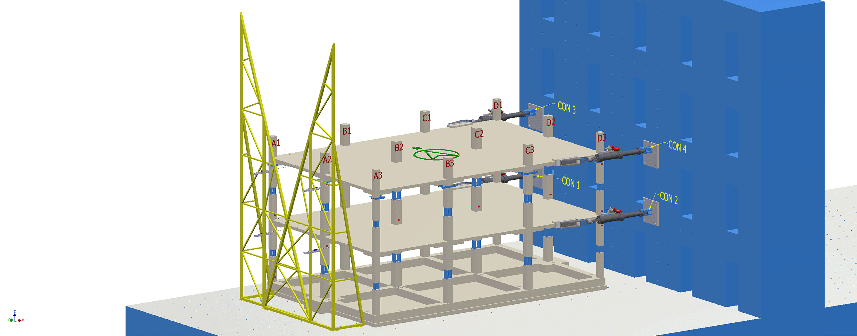
Figure 3. Tri-dimensional schematic view of specimens, including orientation, actuators and column labelling.
During the tests, inclinometers (SEIKA model SBU1) and displacement sensors (GEFRAN 25 mm) were used to monitor the behaviour of the specimen at various locations. Figs. 4 and 5 present the plan view of the first and second slab, respectively, together with the location of the inclinometers and potentiometers. The inclinometers were installed on the bottom surface of the slab to measure local rotations, while the displacement sensors were installed through the slab thickness to record the relative vertical displacement between the top and bottom faces. This arrangement allowed the measurement of slab thickening associated with the development of punching failure.
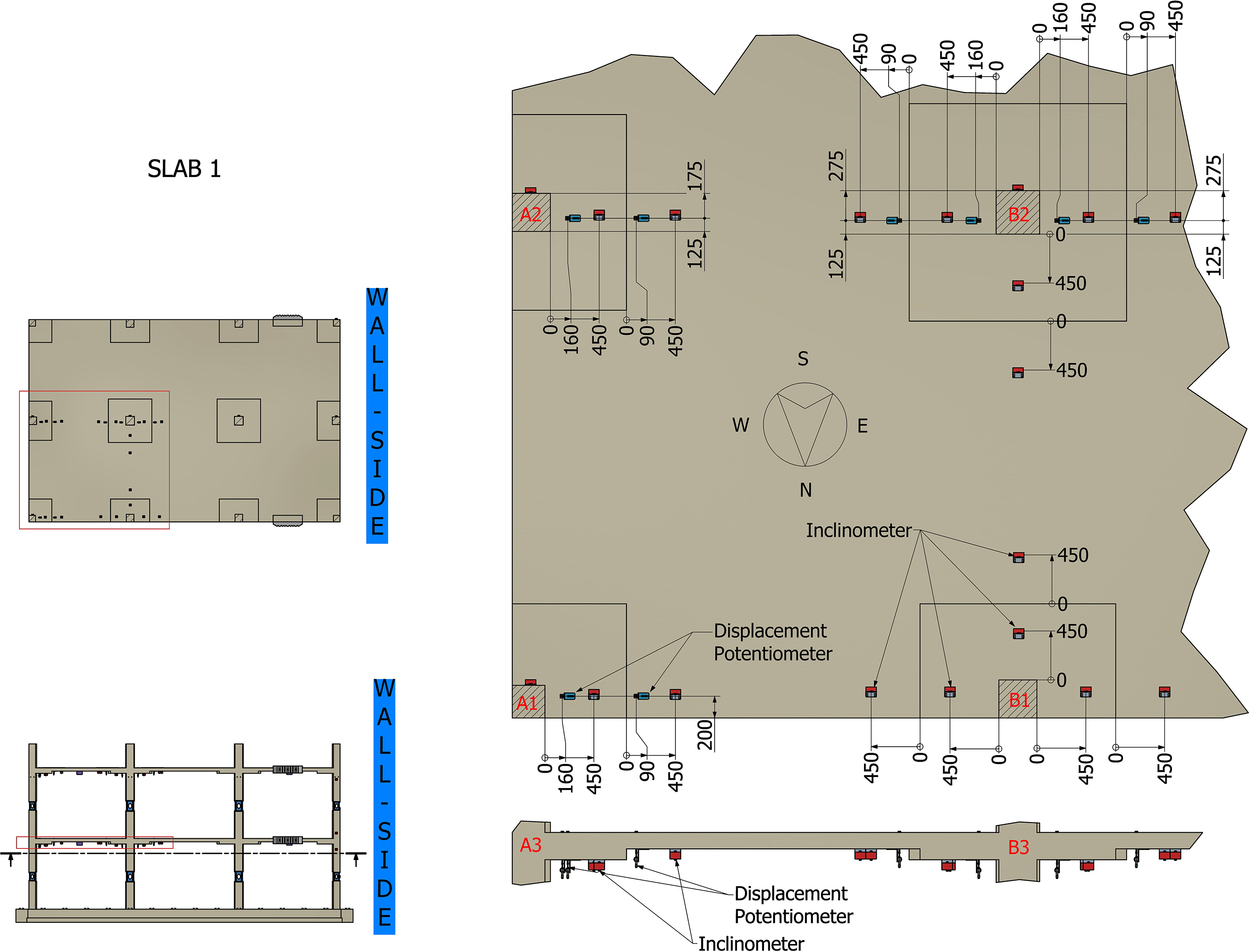
Figure 4. Location of instruments on the first slab (view from below).
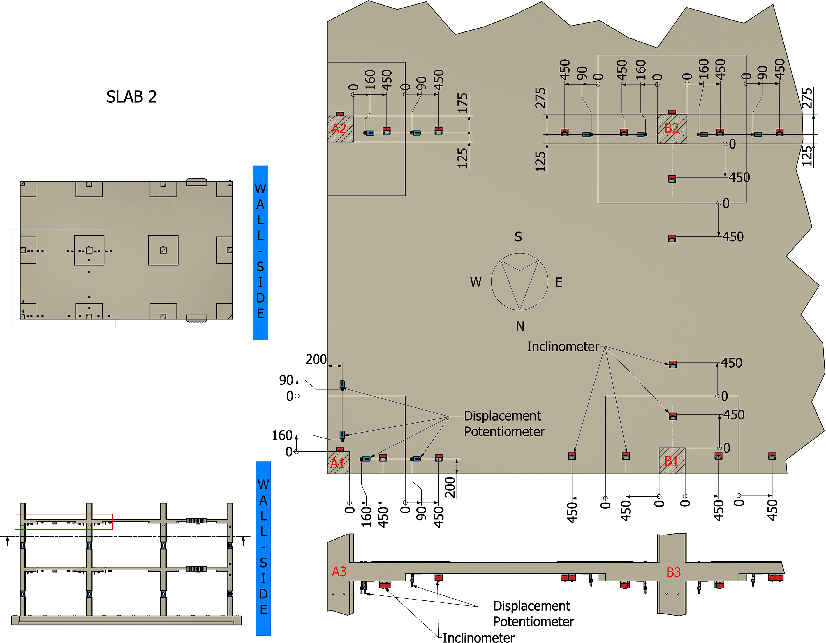
Figure 5. Location of instruments on the second slab (view from below).
Figs. 6 to 8 show the location of the instruments installed on the columns of the three longitudinal (east-west) frames. Inclinometers monitored the rotation at the top and base of certain columns. All the columns also include a load cell installed during the construction phase and used to derive the axial load, the longitudinal shear and the corresponding bending moment. The load cells were developed at JRC and calibrated to derive such internal actions and their variation during the tests based on the readings of 3 strain-gauges. The strain-gauges were installed on the exterior faces of the flanges and in the web of the load cell.
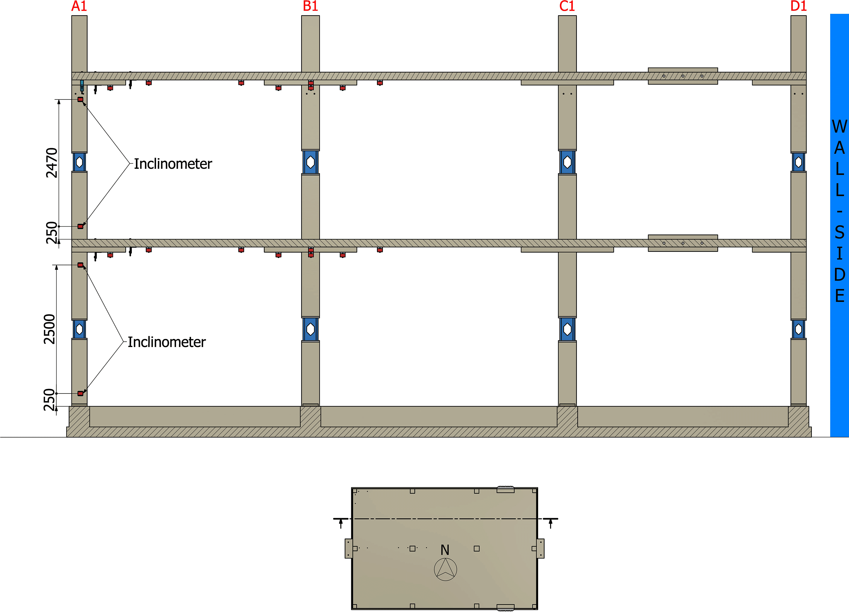
Figure 6. Location of instruments on the north frame (side view).
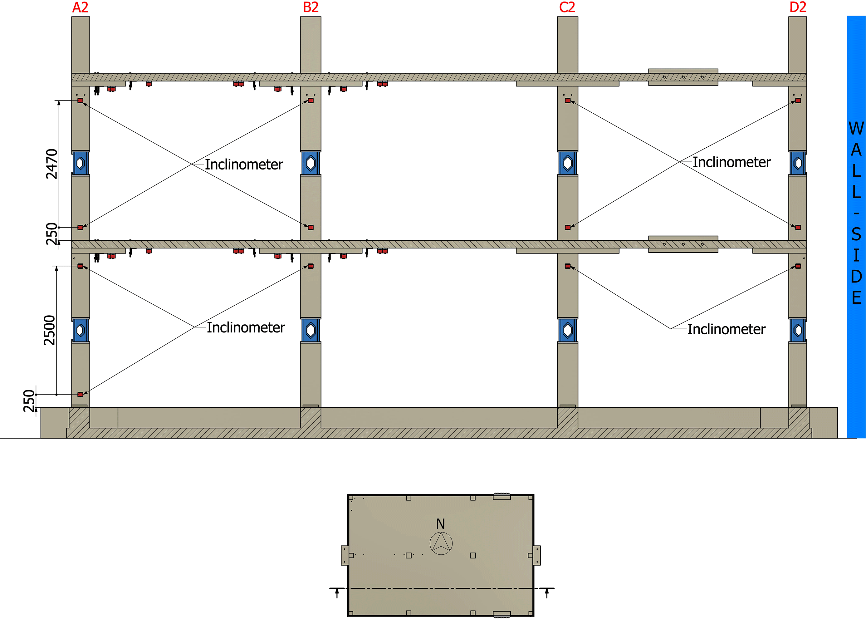
Figure 7. Location of instruments on the central frame (side view).
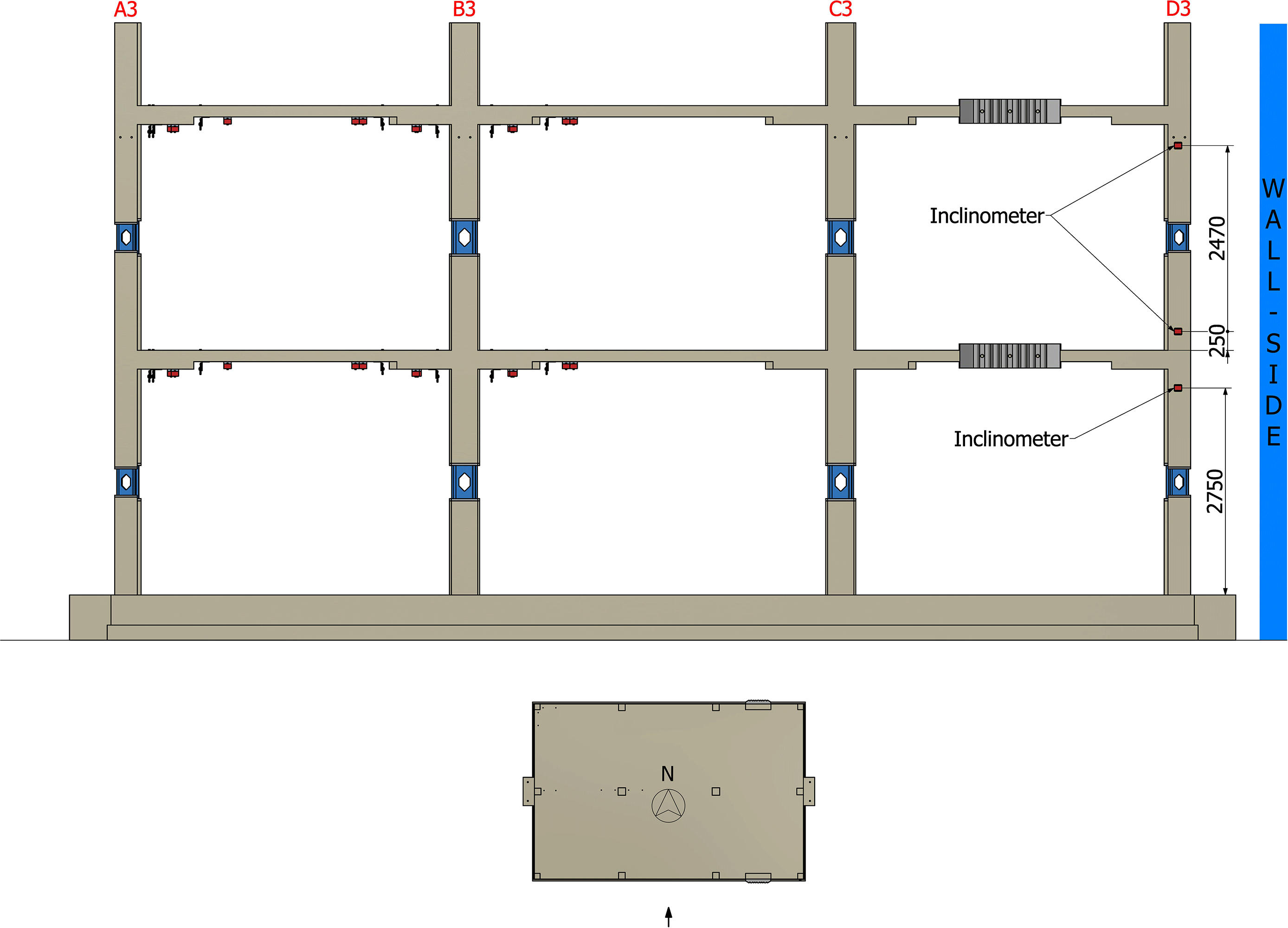
Figure 8. Location of instruments on the south frame (side view).
Tables 3, 4 and 5 present the complete list and the position of the installed sensors. The dataset includes the calibration reports of all the installed instruments, as well as the load cell sensitivities used to convert the strain-gauges readings to internal actions. For additional details about the interpretation of the calibration reports, readers can refer to the Technical Report No JRC139347.16 Furthermore, the complete dataset produced during the calibration and verification experiments on the load cell is available on Zenodo as a separate dataset [https://doi.org/10.5281/zenodo.19204179] as those tests are out of the scope of the RecycleSlab project.
During the tests, ELSAREC, the ELSA REal-time Controller (for further details, refer to17), was used to monitor the response of the specimens running multiple acquisitions in parallel. During the pseudo-dynamic and cyclic tests, the signals of the standard instruments (e.g. inclinometers and strain gauges) were acquired at 10 Hz, while the signals from the control system (e.g. control variables) were sampled at a variable rate. These last signals were recorded at the achievement of each step (record) of the loading pattern, noting that the prototype-time variable common to both acquisition files can be used for synchronisation purposes. For further details, refer to the Technical Report No JRC141264.18
As a safety counter-measure, steel frames were used under the first floor, and for the second-floor steel capitals were fixed to all the columns. These safety systems were designed to support the slabs in case of a total collapse of the slabs but did not interfere with the slab deformation and response during testing (a gap of 10 cm was considered between the systems and soffit of the slab, which allowed the slabs to deform without contact with these elements during testing).
The building specimen will also be subjected to 3D surveying to evaluate the potential and effectiveness of advanced digital surveying techniques for assessing seismic damage in flat slab structures. Laser scanning measurements were carried out both before and after testing, enabling the creation of digital models of the specimen in its pre- and post-test conditions. These models can be examined, measured, compared, and analysed at any time to accurately identify and assess structural damage.
2.3. Test programme and loading input
The objectives of the experimental campaign were: a) verifying the seismic performances of slab frame structures against the requirements of design codes; b) assessing the seismic behaviour beyond what required by standards and c) verifying the effectiveness of strengthening techniques.
Concerning the first objective, the research team performed two pseudo-dynamic (PsD) tests on the specimen in the as-built configuration using input accelerograms which spectra comply with EC8. The input ground motion for the seismic tests was the Y component of signal 00712ya recorded during the MW 6.4 Bingӧl earthquake (Turkey) of 1 May 2003. The original PGA = 2.92 m/s2 was scaled at 31% and 87% for tests SLS (Serviceability Limit State) and ULS (Ultimate Limit State) respectively, to match the corresponding Eurocode 819 elastic spectra. The tests were performed considering only two longitudinal (east-west) translation degrees of freedom (DoF), one for each slab. The PsD tests were implemented adopting the hybrid sub-structuring method in order to simulate the joint effect of the physical model and a virtual reinforced concrete wall. This implied considering additional stiffness and damping matrices, reported in the following equations together with the adopted mass matrix.
After the completion of the PsD tests, the experimental campaign continued performing cyclic tests on two configurations of the specimen, i.e. as-built and with same connection on the second floor retrofitted using post-installed shear reinforcement (connections A1, A2, B1, B2, C3 and D3). Cyclic tests were performed applying a series of three cycles at increasing amplitudes. The control strategy of the test was mixed, imposing a target displacement at the second slab, while force control was adopted at the first slab with a target equal to half of the force applied to the top slab. All cyclic tests were performed at a displacement rate equal to 0.8 mm/s, the maximum achieved top drift was 3% (i.e. 189 mm) on the as-built configuration and 6% (i.e. 378 mm) on the retrofitted specimen.
Table 6 summarises the performed tests included in the dataset. Fig. 9 shows the input accelerogram adopted for the SLS and ULS pseudo-dynamic tests.
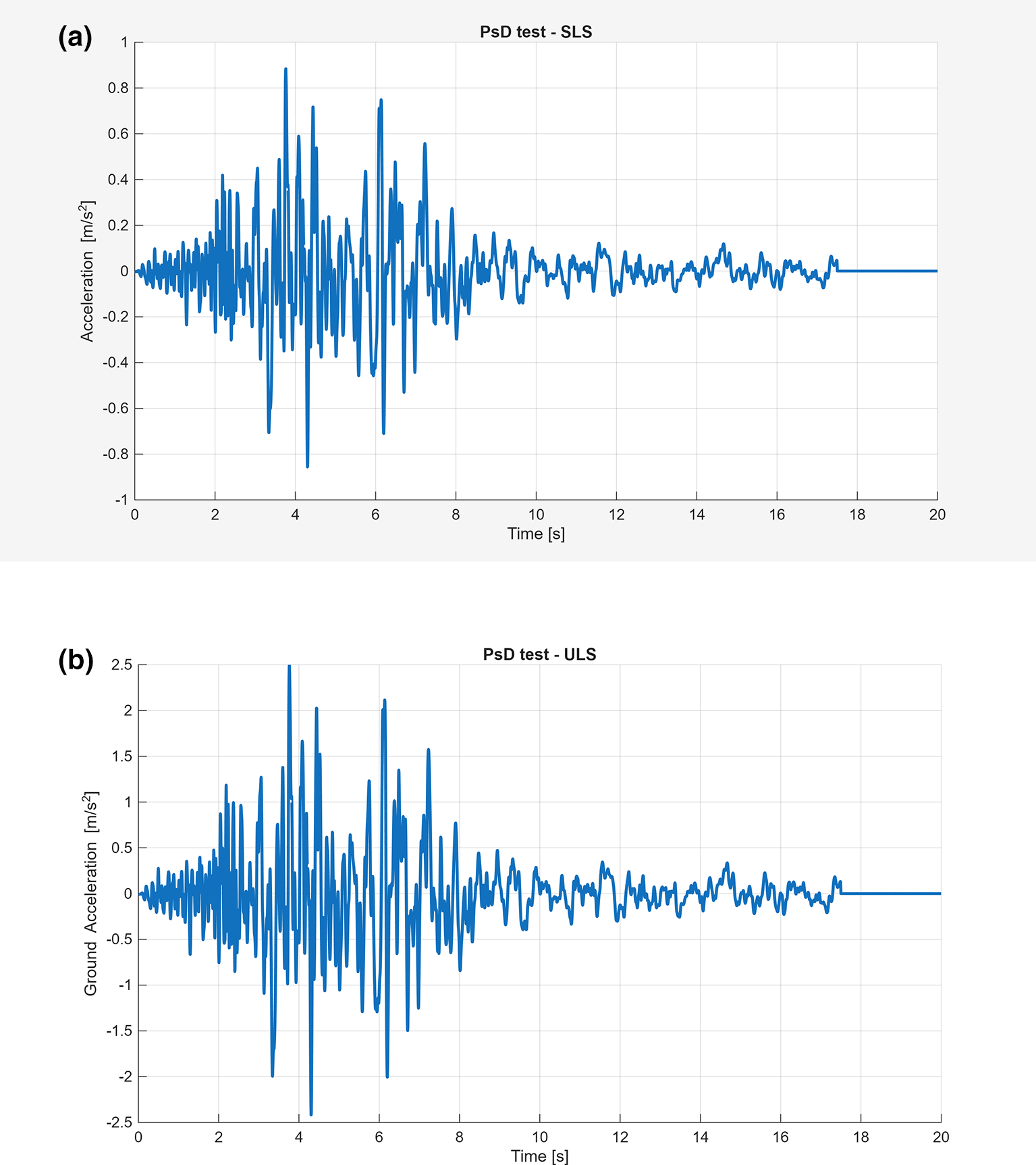
Figure 9. Seismic input adopted for the SLS (left) and ULS (right) pseudo-dynamic tests.
3. Summary of test results
For the SLS test, the maximum recorded drift ratios were 0.17% for the second floor and 0.15% for the first floor (Fig. 10). The maximum base shear (restoring forces) reached were 215 kN for the slab frame and 200 kN for the shear wall (Fig. 11). At these relatively low levels, no significant crack opening occurred in the structure.
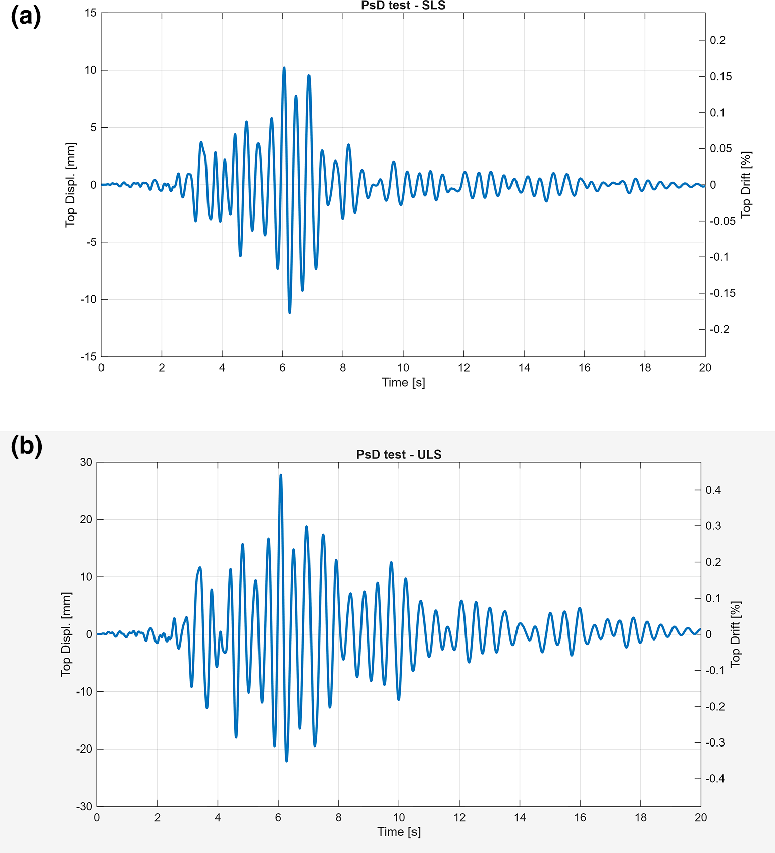
Fig. 10. Top storey lateral displacement for the SLS and ULS.
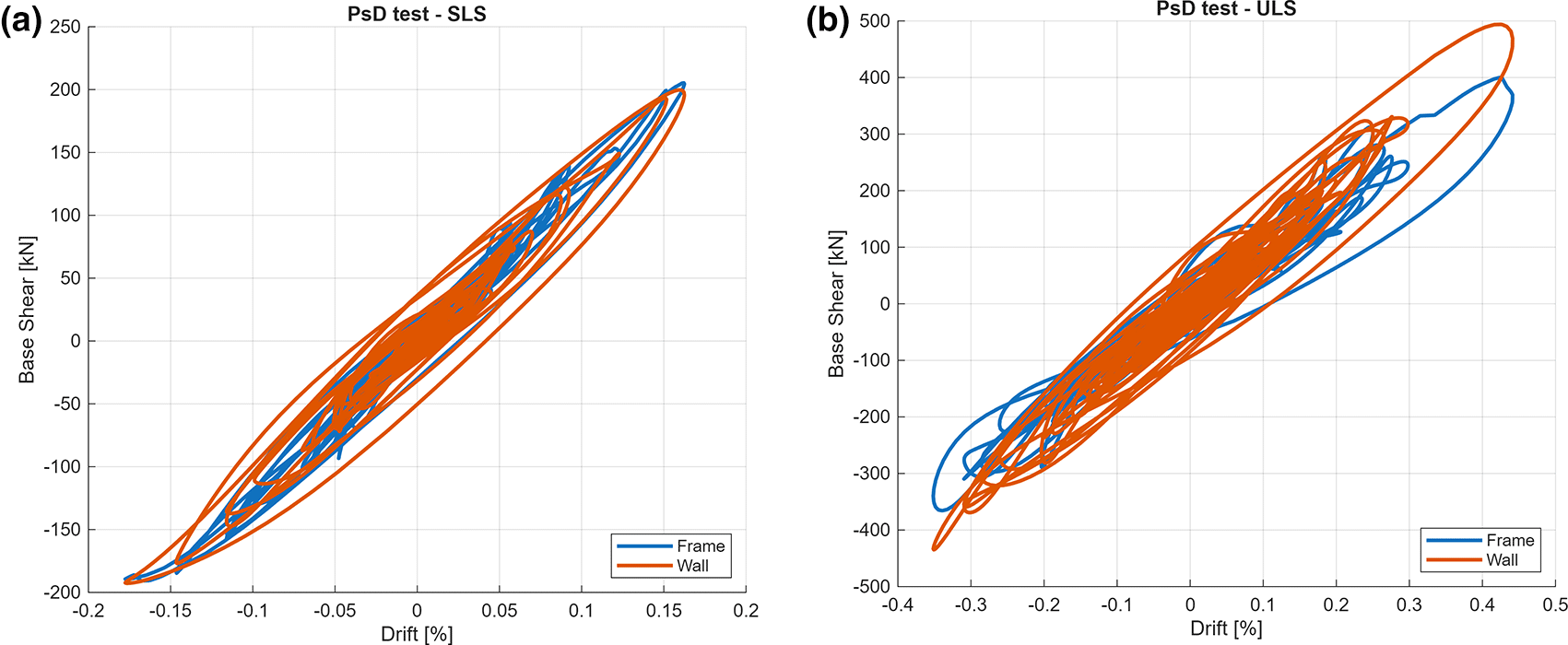
Fig. 11. Base shear forces versus global drift ratio for the SLS and ULS.
(a) Cyclic test up to 3%. (b) Cyclic test up to 6%.
For the ultimate limit state (ULS) test, the maximum recorded drift ratios were 0.43% for the second floor and 0.49% for the first floor, both remaining below the design horizontal drift ratio of 0.6%. The corresponding maximum base shear forces were 401 kN for the slab frame and 494 kN for the shear wall.
The first cyclic test went up to a horizontal drift of 3%. The global response can be observed in Fig. 12, in terms of total base shear in the direction of the applied horizontal load versus the horizontal drift ratio. At a drift ratio of 3%, the structure reached a total base shear of 1292 kN without exhibiting signs of global failure, although significant damage had already developed.
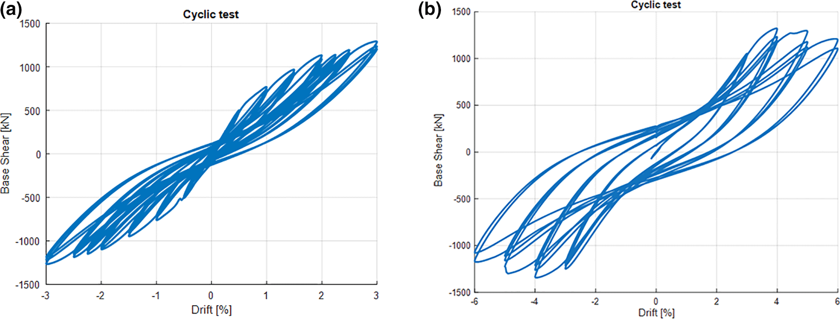
Fig. 12. Cyclic tests: base shear forces (horizontal direction) vs global drift ratio.
After strengthening half of the slab’s connections on the second floor (retrofitted configuration), the cyclic test was resumed, starting at 3% horizontal drift ratio. The global response can be observed in Fig. 12, in terms of total base shear in the direction of the applied horizontal load versus the horizontal drift ratio. From 3% to 4%, it was observed that there was a slight increase in base shear, reaching a maximum of 1343kN. In the subsequent drifts, the backbone curve started to decrease. The test was stopped on the second 6% cycle, since the total base shear force decreased to 80% of the maximum value (the defined global failure criterion). Nevertheless, the structure behaviour up to the 6% horizontal drift ratio was quite stable, being able to redistribute loads from the more damaged connections to the others.
Conclusions
This paper presents the dataset of a large-scale experimental study of a two-storey flat slab building with drop panels constructed using CRCAC, subjected to seismic and cyclic loading.
The global seismic performance was evaluated through pseudo-dynamic (PsD) testing incorporating virtual (numerical) shear walls. The results indicated minimal damage up to a seismic excitation corresponding to the ultimate limit state spectrum.
In the subsequent cyclic horizontal loading phase, applied up to a 3% drift ratio, several slab–column connections experienced severe damage consistent with punching failure. Despite this, the overall structural response remained stable, with no reduction in horizontal base shear capacity.
Following the strengthening of half of the slab–column connections on the second floor, cyclic loading resumed and continued up to a 6% drift ratio, at which point the predefined global failure criterion was reached (total base shear reduced to 80% of its peak value). Even so, the structure maintained a stable behaviour, demonstrating the ability to redistribute loads from the most damaged connections to those less affected.
Overall, the results demonstrate that flat slab structures can exhibit satisfactory global performance under seismic and cyclic loading, provided that appropriate design and reinforcement detailing are employed—particularly the inclusion of integrity reinforcement at all connections. The use of CRCAC did not appear to have a significant adverse effect on the structural behaviour of the building.
Ethics and consent
Ethical approval and consent were not required.
Data availability
Zenodo. RecycleSlab - Structural Behaviour of Recycled Aggregate Reinforced Concrete Flat Slabs with Drop Panels under Seismic and Cyclic Actions: dataset. https://doi.org/10.5281/zenodo.19189241.20
This project contains the following underlying data:
• RecycleSlab_v1.zip. The zip file, once extracted, allows accessing to the whole dataset. The information is accessible to a standard filesystem structure. Due to its complexity, in order to understand the structure of the shared dataset, the reader should refer to the Technical Report No JRC141264.18
• A short list of the main contents includes (i) details of the specimens, (ii) applied loading patterns, (iii) details and calibration reports relative to the installed instrumentations (for further details on the calibration procedure refer to the Technical Report No JRC13934716). Besides, for each test, the dataset includes: (i) raw data as recorded by the acquisition system of the ELSA lab, (ii) processed data for an easier access to the output of the monitoring, (iii) graphical representation of the main response quantities.
Data is available under the terms of the CC BY 4.0 license.
The paper briefly presents the ERIES-RecycleSlab project, including all relevant information regarding the specimens, measuring equipment, test setup and test procedure and any information needed to replicate, validate, and/or reuse the results included in the shared dataset. Future publications will include detailed analyses and discussion of the results, which are out of the scope of this paper. The dataset, gathering quantitative information and metadata, is made available by the authors in line with the requirement of the framework of the ERIES Project [Grant agreement ID: 101058684, https://doi.org/10.3030/101058684].
Acknowledgements
The authors acknowledge the contributions of all team members of the ERIES-RecycleSlab project who are not authors of this particular paper. The authors are also thankful for all the help and support of the staff at the JRC ELSA facility, without whom this experimental campaign could not have been successfully completed.
References
- 1.
United Nations:
Transforming our world: The 2030 Agenda for Sustainable Development.2015.
- 2.
Regúlez B, Faria DMV, Todisco L, et al.:
Sustainability in construction: The urgent need for a new ethics.
Struct. Concr.
2023; 24(2): 1893–1913. Publisher Full Text
- 3.
Pacheco J, de Brito J , Lamperti Tornaghi M:
Use of recycled aggregates in concrete – Opportunities for upscaling in Europe.
Luxembourg:
Publications Office of the European Union;
2023.
- 4.
Ramos A, Marchão C, Pacheco JN, et al.:
A review of punching behavior of slab–column connections with recycled coarse aggregate concrete.
Struct. Concr.
2025; Volume 26(2): p.1388–1401. RAMOS ET AL. Publisher Full Text
- 5.
Fardis M, N.:
Flat slabs as primary seismic elements in second-generation Eurocode 8.
Bull. Earthq. Eng.
2021; 20: 4025–4063. Publisher Full Text
- 6.
Coronelli D, Lamperti Tornaghi M, Martinelli L, et al.:
Testing of a full-scale flat slab building for gravity and lateral loads.
Eng. Struct.
2022; 243: 112551. Publisher Full Text
- 7.
Muttoni A, Coronelli D, Lamperti Tornaghi M, et al.:
Deformation capacity evaluation for flat slab seismic design.
Bull. Earthq. Eng.
2022; 20: 1619–1654. Publisher Full Text
- 8.
Ramos AP, Isufi B, Marreiros R, et al.:
Seismic performance of strengthened slab-column connections in a full-scale test.
J. Earthq. Eng.
2022; 27(9): 2299–2318. Publisher Full Text
- 9.
Ramos A, Carla M, Dario C, et al.:
Project RecycleSlab - Structural Behaviour of Recycled Aggregate Reinforced Concrete Flat Slabs with Drop Panels Under Seismic and Cyclic Actions.
Lecture Notes in Civil Engineering.
2025; 718 LNEC: 206–216.
- 10.
Ramos AP, Enfedaque A, Marchão C, et al.:
Project ERIES-RecycleSlab - Seismic behaviour of flat slabs with drop panels made with reinforced recycled aggregate concrete
2026 International Workshop in Engineering Research Infrastructures for European Synergies (ERIES-IW2026). Pavia, Italy, May 2026.
2026.
- 11.
Ramos AP, Enfedaque A, Marchão C, et al.:
Structural Behaviour of Recycled Aggregate Reinforced Concrete Flat Slabs with Drop Panels under Seismic and Cyclic Actions (Project ERIES-RecycleSlab).
presented in the 7th fib Congress 2026, Lisbon, Portugal, June 2026.
2026. Publisher Full Text
- 12.
Pacheco J, Capucha F, Pinho Ramos A, et al.:
Recycled aggregate incorporation and drop panel design for flat slab concrete structures: Environmental benefits through life cycle assessment (Project ERIES-RecycleSlab).
7th fib Congress 2026, Lisbon, Portugal, June 2026.
2026.
- 13.
Fecko T, Ľudmila K, Pinho RA, et al.:
Punching shear behaviour of full-scale slab-column connections cast from concrete with coarse recycled aggregate.
Eng. Struct.
2025; 345. Publisher Full Text
- 14.
Fecko T, Ľudmila K, Pinho RA, et al.:
Punching Shear Behavior of Full-Scale Flat Slabs Cast From Coarse Recycled Aggregate Concrete.
fib Symposium, Antibes, France, June 2025.
2025; p.2451–2456. (2025b).
- 15.
Ramos AP, Carla M, Rui M, et al.:
Punching behavior of slab-column connections with recycled coarse aggregate concrete
fib Symposium, Antibes, France, June 2025.
2025; p.2106–2115.
- 16.
Peloso S, Molina FJ, Lamperti Tornaghi M, et al.:
ELSA - Procedure for calibration and verification of displacement and rotation measuring systems.
Luxembourg:
Publications Office of the European Union;
2024; vol. 2024. . Publisher Full Text
- 17.
Peroni M, Pegon P, Molina FJ, et al.:
Ethernet-Based Servo-Hydraulic Real-Time Controller and DAQ at ELSA for Large Scale Experiments.
J. Earthq. Eng.
2022; 26(15): 7657–7688. Publisher Full Text
- 18.
Peloso S, Molina FJ, Lamperti Tornaghi M, et al.:
ELSA - Structure of the experimental datasets.
Luxembourg:
Publications Office of the European Union;
2025. JRC141264. Publisher Full Text
- 19.
CEN:
EN 1998–1. Eurocode 8: Design of structures for earthquake resistance – Part 1: General rules, seismic actions and rules for buildings.2004.
- 20.
Peloso S, Peroni M, Molina FJ, et al.:
RecycleSlab - Structural Behaviour of Recycled Aggregate Reinforced Concrete Flat Slabs with Drop Panels under Seismic and Cyclic Actions: dataset. [Dataset].
Zenodo.
2026. Publisher Full Text