The developed motor follows a direct-drive architecture, in which the rotor is press-fitted directly onto the axle, enabling torque transmission without intermediate mechanical elements such as gearboxes, chains or belts. This solution35 offers significant advantages in terms of compactness, mechanical simplicity, and maintenance reduction—key factors in railway applications. The press fit was sized using conventional interference-fit calculations to transmit the maximum torque considered in the design. The installation retains the existing disc-brake hardware without modification.
The motor housing has been shaped to match the available space envelope around the axle while ensuring mechanical rigidity and thermal performance. It is bolted in a cantilever arrangement with no dedicated motor bearings. Combined with the integrated oil-cooling system, this architecture enables high torque density within a tightly constrained volume.
Figure 6 shows the general architecture of the motor assembly in the available space between the wheel and the axlebox.
3.2 Railway standard compliance
In the context of direct-drive railway traction, mechanical integration is not limited to spatial packaging or fixation strategies—it must ensure that the entire motor assembly can withstand real-world operational loads, vibrations, and shocks throughout its service life. This becomes especially critical when the motor is axle-mounted, as both the rotor and stator are directly exposed to track-induced mechanical stresses. Therefore, compliance with relevant railway structural and vibrational standards is one of the most demanding aspects of mechanical integration and plays a key role in the overall reliability of the system.
To rigorously validate the motor design against these standards, a comprehensive finite element analysis (FEA) methodology was developed and implemented.36 This robust approach was specifically tailored to evaluate the structural integrity of the system under both severe static and dynamic loading conditions. Independent, high-fidelity models were established for the stator and rotor assemblies to accurately capture their distinct structural behaviours.
To ensure a conservative and reliable assessment, the fixed components—including the stator, the housing, the cooling system and containment ring—were represented in their installed cantilever configuration.
Regarding the rotor, the analysis focused on the magnet retention system, which relies on adhesive bonding within the slots rather than an interference fit. To accurately capture this behaviour, two modelling approaches were employed: for static scenarios, the adhesive was simplified as a 0.1 mm-thick layer; for dynamic simulations, it was modelled with springs that represented the stiffness of this effective bonded area using the adhesive properties supplied by the manufacturer. Since there are no specific standards dictating the exact modelling parameters for adhesive in motor slots, a conservative heuristic approach was adopted based on the manufacturer’s empirical know-how and extensive engineering experience. To account for the inherent variability in the adhesive application process, such as uneven distribution, void formation and long-term thermo-mechanical ageing, the effective bonding area was deliberately restricted to 30%. This assumption guarantees a conservative worst-case scenario for the structural assessment. It is important to note that the adhesive is treated as a secondary safety measure; the rotor slot geometry is designed to mechanically retain the magnets and withstand operational loads even in the event of adhesive failure, satisfying the requirement for dual retention mechanisms. Both assemblies were discretised using high-order tetrahedral elements with local mesh refinement applied to contact interfaces and stress concentration regions.
To establish a consistent and robust acceptance criterion across all evaluated load cases, distinct failure theories were applied depending on the nature of the materials. For ductile metallic components, such as the structural frame and rotor laminations, the von Mises equivalent stress criterion was employed, with the maximum allowable stress strictly limited to the material's yield strength to prevent any plastic deformation. Permanent magnets, however, are inherently brittle materials characterised by a significant disparity between their tensile and compressive strengths. Consequently, their structural integrity was assessed using the Mohr-Coulomb stress criterion for brittle materials37 . This approach accurately captures the asymmetric failure behaviour of brittle materials, providing a highly reliable safety assessment of the magnetic poles under the severe conditions dictated by the railway standards.
3.2.1 Assessment under static structural load cases
To assess structural integrity under operational conditions, the motor assembly was evaluated using selected load cases derived from EN 13749:2011.38 Given the rigid attachment of the motor housing to the axlebox, these load cases were adopted by analogy as a reference for the structural assessment. Static structural simulations were used to evaluate the assembly under the selected loads and load combinations. This assessment characterises the response to the adopted loading conditions and does not establish full compliance with the standard.
In the case of the stator and housing, the loads acting on the assembly are the maximum torque, self-weight and inertial loads due to the acceleration of the train. For this purpose, the maximum short-circuit torque was considered and applied to the stator slots, since it is the peak torque the motor must withstand instantaneously. The weight and inertial loads are especially relevant since the motor is fixed in a cantilever configuration, separating the centre of gravity from the fixed support and elevating the mechanical stress in the joints. In this analysis, controlling the maximum displacement at the cantilevered end is crucial to maintain the air gap clearance and avoid physical interference between the rotor and the containment ring of the cooling system. Due to the properties of the assembly, this simulation modelled the whole assembly without applying symmetry. The bolted joints inside the assembly were simplified and considered as bonded connections. However, special attention was given to the bolted joint between the housing and the axlebox, considering a pretension represented by a nominal axial stress of 430 MPa in the bolts according to the VDI 2230:2014 standard.39
The following results detail the stress and displacement levels observed in the structural parts of the motor under standard-defined operational loads, verifying the adequacy of the active components for axle-mounted integration. The maximum stress in the aluminium parts was found to be 90 MPa, with a maximum displacement of 0.04 mm, remaining well within the safety margins of 7075 aluminium alloy, whose yield strength is 460 MPa, providing a safety margin of 5.11 (see
Figure 9). A local peak of 548 MPa was observed in the simulation at the contact area of the bolted interface. However, this is attributed to boundary conditions applied in the model where the axlebox was not explicitly included. Therefore, the concentration is not physically representative of the complete system and does not affect the validity of the stress evaluation in the motor’s structural parts.
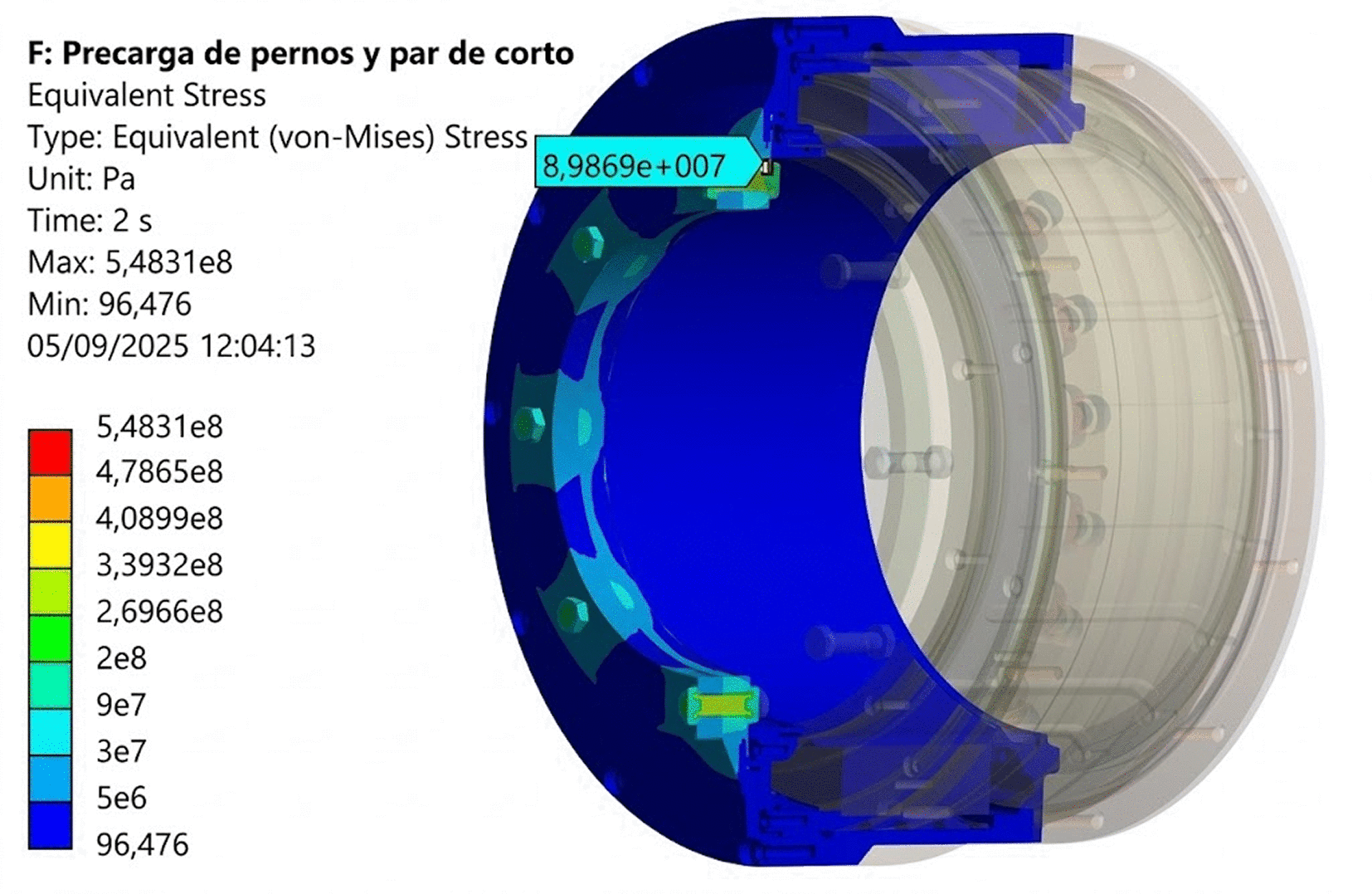
Figure 9. Equivalent von Mises stress map in the housing and flange under operational loads.
These results confirm the motor’s structural adequacy for axle mounting, ensuring robustness against all defined operational loads while preserving alignment and air gap stability.
For the rotor, the same maximum torque was applied, but in this case the most critical load is the rotational speed. According to the railway electric traction standard EN 60349-2:2010,40 the machine must withstand an overspeed of 20% above its maximum operating speed. Although the nominal maximum train speed for this application is 360 km/h (~2275 rpm), the specific use case requirements demand structural integrity up to 400 km/h (~2500 rpm). Therefore, a conservative approach was adopted by applying the margin to 2500 rpm and assessing the motor at 3000 rpm.
The results for the lamination confirm that the peak stress levels remain below the yield strength (359 MPa at 150 °C according to a previous in-house material test), providing an adequate safety margin (see
Figure 10 and
Table 5). Moreover, rotor deformation does not compromise air-gap stability or the mechanical retention of the magnets. For the magnets, the safety factor calculated using the Mohr-Coulomb criterion is even higher (see
Figure 11 and
Table 5). The stress levels remain well below the limit according to the diametral tensile stress for the most conservative scenarios reported in the literature.18
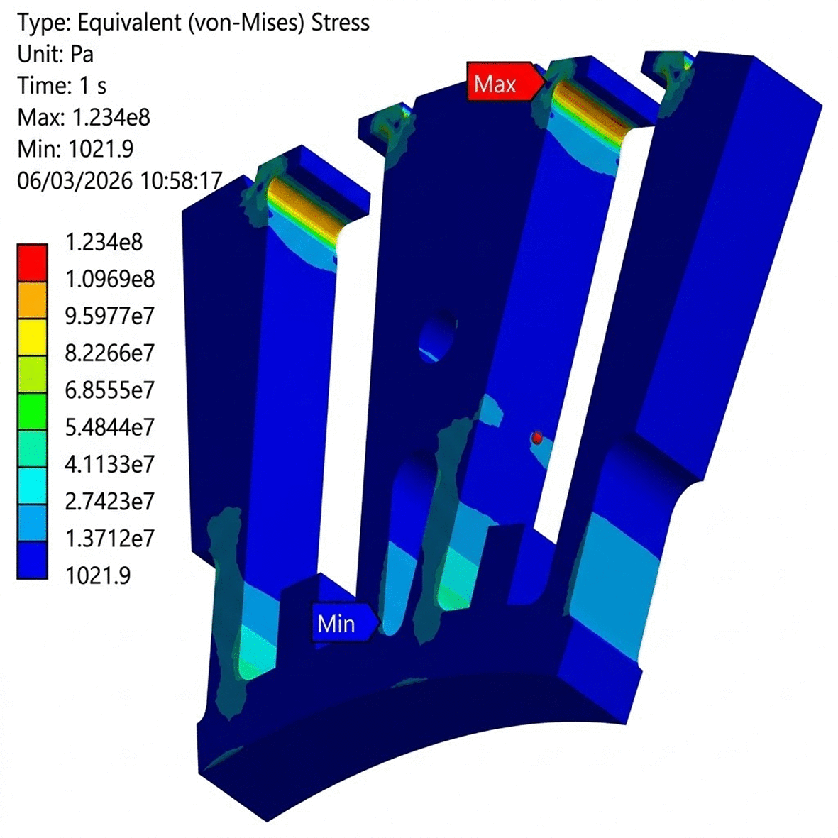
Figure 10. Equivalent von Mises stress map in the rotor for unglued magnets under operational loads.
Table 5. Safety factor for rotor components.
| Component | Glued magnets |
Unglued magnets |
|---|
| Rotor lamination
| 6.59
| 2.91
|
| Permanent magnets
| 8.87
| 7.90
|
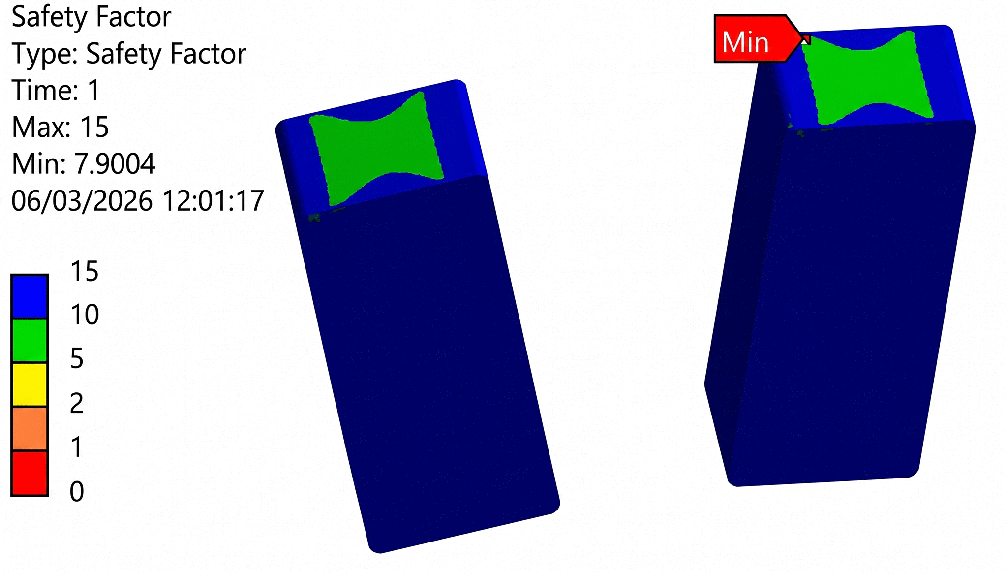
Figure 11. Safety factor according to the Mohr-Coulomb stress criterion for unglued magnets under operational loads.
This mechanical validation confirms that the active parts of the motor comply with the structural requirements of the application and show no plastic deformation. Both the rotor and stator demonstrate a mechanically sound response under nominal and extreme conditions, ensuring air gap stability and long-term operational reliability.
3.2.2 Assessment under dynamic load cases
To validate the motor’s resistance to mechanical shocks and vibrations during railway operation, simulations have also been performed in accordance with EN 61373:2010,41 which specifies the test requirements for vibration and mechanical shock in railway equipment. The motor was evaluated under Category 3 (Axle-Mounted Equipment), the most demanding profile defined by the standard. Prior to the spectral analysis, a modal extraction was performed to characterise the dynamic stiffness of the assemblies. Natural frequencies and mode shapes were extracted up to 2000 Hz—significantly above the standard’s cut-off frequency—to ensure modal mass participation in the subsequent superposition steps with a ratio of effective mass to total mass of over 0.9.
The following tests were simulated using FEA tools on both the stator and rotor assemblies:
The first two were conducted using random vibration profiles defined by power spectral density (PSD) curves using the modal superposition method. These excitation signals are analogous in both simulations, exciting the sample in all directions simultaneously from 10 to 500 Hz. The difference between the two tests lies in the vibration intensity for the vertical, transverse, and longitudinal excitations as shown in
Table 6. The higher intensity in the second test represents the effects of ageing in the materials. A conservative damping ratio of 2%, typical of standard bolted assemblies, was applied, ensuring the design's reliability even under unfavourable conditions. All simulation results were evaluated using a 3σ (99.7%) statistical level, in accordance with the standard’s prescribed methodology for random vibrations and ensuring structural integrity under the most restrictive scenario.
Table 6. Equivalent RMS accelerations FOR random vibration excitations according to EN 61373:2010.
| Direction | Functional random vibration |
Long-Life endurance |
|---|
| Vertical
| 3.88 g
| 14.69 g
|
| Transverse
| 3.47 g
| 13.16 g
|
| Longitudinal
| 1.73 g
| 6.56 g
|
The shock test was simulated using a transient dynamic model in the time domain, applying half-sine acceleration pulses of 1000 m/s2 (100 g) lasting 6 ms, independently in all three axes (vertical, longitudinal and transverse) with a time step of 0.5 ms. Unlike a static equivalent analysis, this time-domain approach captures the inertial effects and the dynamic amplification of the internal components. This is particularly critical for the permanent magnets and the cantilevered stator overhangs, which may experience local acceleration peaks higher than the input pulse due to their own flexibility. The acceptance criterion mandated a safety factor greater than 1 against yielding, ensuring that even under these extreme, rare events, the motor components suffer no permanent deformation and maintain their geometric tolerances for continued operation, with particular attention to the air gap.
The results discussed below focus on the mechanical response of the motor under shock and vibration conditions, emphasising the integrity of structural and sealing components under dynamic loading.
The most critical behaviour was found in the stator assembly due to its cantilevered mounting. To improve stiffness without compromising mass, 7075 aluminium was selected for the housing and axlebox interface components, contributing to higher power density and resistance to both static and dynamic loads.
The most critical stress distribution was observed during the long-life vibration test. In this case, the peak stress reached 261 MPa, localised at the motor's mounting interface with the axlebox (see
Figure 12). This result, while representing the worst-case scenario across all simulated conditions, remains well below the yield strength of 7075 aluminium, providing a safety margin greater than 1.5 (excluding the local peak stress due to the stress concentration at the bolted interface) and confirming the structural integrity of the design under extended vibration exposure.
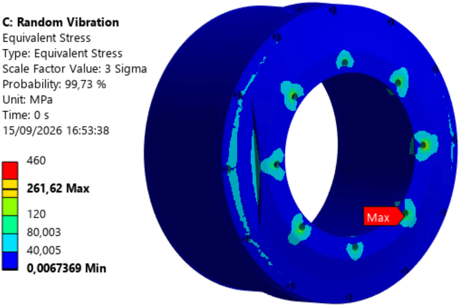
Figure 12. Equivalent von Mises stress map under dynamic loads (long-life test).
The 1.3 mm physical air gap proved sufficient to prevent rotor-stator contact under the worst-case displacement scenario. The most critical test in terms of displacement is the transverse shock, with a total displacement of 0.49 mm providing a gap-to-displacement ratio of 2.65 (see
Figure 13).
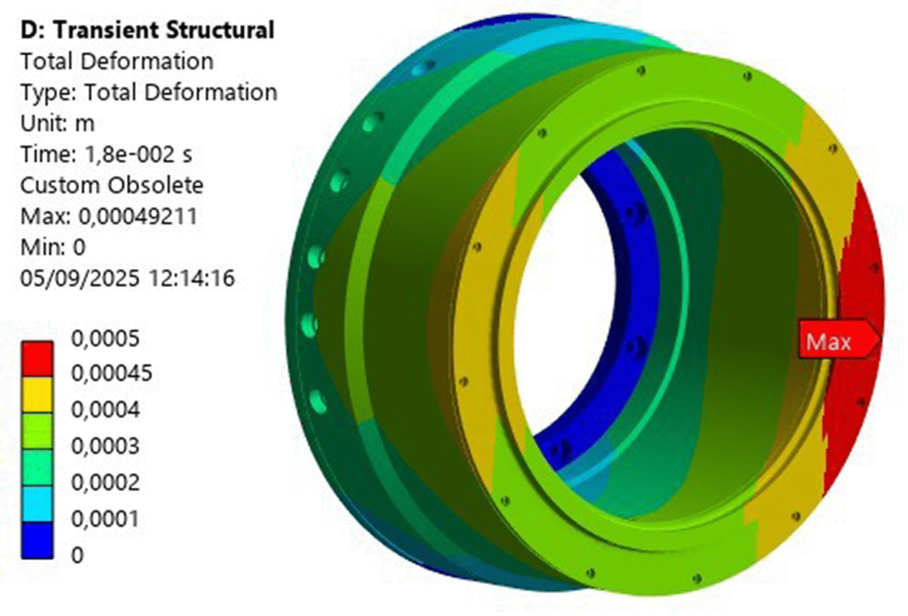
Figure 13. Displacement map under dynamic loads (transverse shock).







