This paper utilizes a MILP formulation to optimize radial CGs. Since the focus is on the cabling problem, the layout is assumed to be known. In other words. the WTs and substations locations have been established. A multi-criteria optimization addresses costs and the proposed PCR. From the cost perspective, the formulation is based on 13,18. In a post-optimization stage, Monte Carlo simulations assess the reliability of the obtained CGs and analyze the results against PCR.
2.1 Cost-based formulation
Based on 13,18, the CG is a directed graph spanning from the substation. Binary variables ui,j,t represent cables connecting i ∈ 𝒩0 to j ∈ 𝒩 carrying the nominal power generation from t WTs. Note that this convention for the direction of the graph edges implies power flowing from j to i. The decision variables u do not depend on the cable types. If a particular cable transports power from t WTs, it is implicit that the optimal cable type is the least costly to support t WTs. Figure 1 exemplifies a CG following the described formulation, where binary variables associated with existing cables transporting coherent power are equal to one. Any other binary variable is equal to zero.
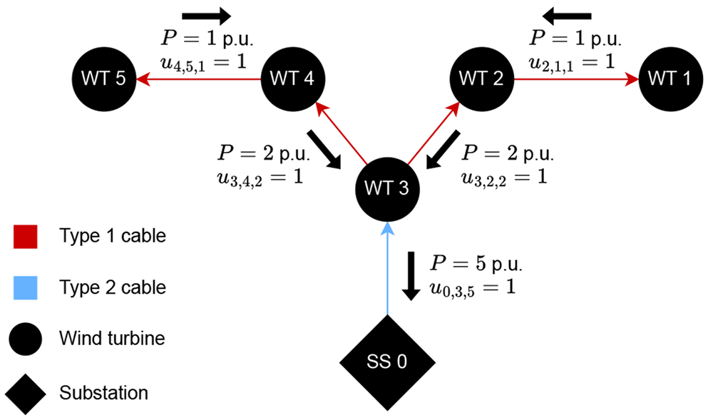
Figure 1. Example of a directed graph representing a CG with 1 substation, 5 WTs, and cables of type 1 and 2 with capacities of up to 3 and 5 p.u., respectively.
Function (ℱ1) represents the purchase and installation cost of the cables. The function depends on the lengths of cables and their prices per distance, as described by Equation 1.
In Equation 1, α is an auxiliary cost vector indicating the price per distance of the cables based on the number of downstream WTs. Let us take a set of cable types 𝒞 = {c1, ... , cnct} with purchase plus installation prices given by 𝒫 = {p1, ... , pnct} and capable of transporting power from up to 𝒦 = {k1, ... , knct} WTs. Observe that set K translates to nominal power transportation capability, in p.u. Vector α comes from Algorithm 1.
Algorithm 1: Pseudo-code linking each nominal power (p.u.) transportation possibility (1, 2, ... , knct − 1, knct) with the least costly cable type with enough capacity. The values are stored in α.
aux = 1
for x in 1 to knct, by 1, do
if x ≤ kaux then
αx = paux
else
aux = aux + 1
αx = paux
end
end
Still in Equation 1, Qi is the highest quantity of WTs that can be downstream of i ∈ 𝒩0. Note that Qi = knct if and only if i is a substation. Otherwise, Qi = knct − 1.
From the x and y coordinates of WTs and substations, Equation 2 calculates Lij according to the Euclidean distances among the OWPP components. Matrix L contains the lengths of the potentially installed cables.
Ahead are the constraints describing the cable connectivity of each WT, the cable-crossing prohibition, the power flow, and the number of direct connections to the sub-stations. Equation 3 states that each j ∈ 𝒩 receives one and only one connection, which comes from i ∈ 𝒩0 and transports power equivalent to the nominal generation of t downstream WTs.
Regarding the cable-crossing prohibition, Bauer and Lysgaard24 state that crossing cables may cause excessive heating that would require the cables to have insulation against each other. Furthermore, since one cable would be buried deeper than the other, maintenance would become more costly. Let us take two distinct cables ij1 and j2j3, with i ∈ 𝒩0 and j1, j2, j3 ∈ 𝒩. If installation implies crossing the cables, either Equation 4 or Equation 5 apply. If i is not a substation, the former must be implemented. Otherwise, the latter is valid. It is noteworthy that if any of the elements i, j1, j2, j3 is the same as one of the others, it is certain that crossing does not occur.
Equation 6 ensures that the quantities of WTs upstream and downstream of each WT j ∈ 𝒩 are coherent. Since the number of connected WTs is equivalent to the nominal power in p.u., it is critical to observe that Equation 6 also ensures power flow conservation.
Equation (7) imposes a bound on the maximum quantity of cables that can directly reach a substation.
Equation (8) states that the generation from all WTs must reach the substations. Observe that the | | operator denotes the set cardinality.
If ui,j,τ = 1, the number of connections outgoing j with t downstream WTs must be smaller than or equal to ⌊ (τ − 1) / t ⌋, with ⌊ ⌋ denoting the floor operation. Based on this property, Cerveira et al.13 proposed the constraints in Equation 9 and Equation 10 to reduce the solution space without compromising optimality.
In terms of connectivity, Equation 11 yields a |𝒩0| x |𝒩| matrix (u′) that does not relate to the number of downstream WTs. From the interconnection perspective, u′ defines the CG since it indicates which cables exist. Note that Equation 11 is not a constraint to the optimization problem. However, u′ is necessary for the upcoming MCA assessments.
2.2 The proposed power capacity risk
This work seeks to comprehensively address the reliability of radials CGs. To model the proposed PCR, Equation 12 defines a new variable (δ) to the problem. Note that δj is simply the nominal power flowing through WT j’s cable weighed by the cable’s length. Thus, function ℱ2 (Equation 13) is the cumulative sum regarding the power flow of all cables weighed by their lengths. As demonstrated further, ℱ2 reflects the effects of cable failures and strongly correlates to reliability. In summary, ℱ2 quantifies PCR.
The reason for weighing the flowing power according to the cable lengths is that longer cables are more prone to failures. After all, it is usual in the literature to model failure rates of cables as a certain number of occurrences per period per length, such as in 15,22. Thus, this approach penalizes the utilization of longer cables as these tend to experience failures more often than shorter cables. Subsequent sections show that minimizing the length-weighed cumulative power flow (ℱ2) makes the radial system more spread. In other words, more branches are created. Thus, the impact of cable failures tends to decrease due to less power curtailment upon contingencies. By normalizing the cost and PCR, Equation 14, subjected to Equation 3 to Equation 10 and Equation 12, defines the optimization problem.
where: 𝒲 is a weighing factor in [0,1] that balances the two optimization criteria; and are the normalized ℱ1 and ℱ2 in [0,1]. The following section explains the normalization procedure.