Introduction
Additive manufacturing (AM), commonly known as 3D printing, has revolutionized manufacturing through its adaptability and efficiency. This layer-by-layer process simplifies the production of intricate components from digital models that would be laborious using traditional methods. Despite these advances, there are some challenges with metal AM, particularly poor surface quality. Post-processing techniques are essential to meet industry standards. Various methods, including PeP, have emerged to overcome this challenge. PeP, a unique process that combines electrolysis and plasma reactions, quickly delivers a shiny surface. The schematic representation of the PeP setup can be found in Figure 1. Particle blasting is another common technique to clean the printed parts by removing unmelted or partially melted powder clusters from the surface and achieving a better surface quality. PeP of parts with a very high initial surface roughness can be a time-consuming processing technique to achieve the desired lower surface roughness values. This can be solved by combining PeP with other post-processing techniques and determining an appropriate sequence and processing time for each technique to optimize the workflow. This study investigates the effect of PeP on stainless steel samples and looks for the ideal combination with particle blasting for better surface quality.
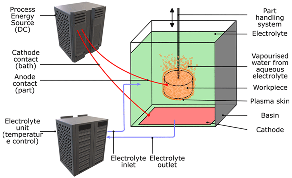
Figure 1. Schematic of PeP setup4.
Methods
Altogether six stainless steel samples were prepared for the experiments and three are shown in Figure 2. Samples were fabricated using the laser powder bed technique at the Technion- Israel Institute of technology. The parts were designed to include some complex features and logos of all the institutes involved in the project, to demonstrate and analyze the capability of the PeP process to improve the surface quality of AM samples. The samples were characterized using the MarSurf CM explorer microscope for surface roughness analysis. In this study, the samples are assigned numbers based on the post-processing cycle1 (see Table 1).
Table 1. Post processing stages of different samples.
| Part No. | Process 1 | Time (min.) | Process 2 | Time (min.) | Process 3 | Time (min.) |
|---|
| 1 | Particle blasting | 10 | | | | |
| 2 | Particle blasting | 10 | Particle blasting | 10 | | |
| 3 | Particle blasting | 10 | Particle blasting | 10 | Particle blasting | 10 |
| 4 | Particle blasting | 10 | PeP | 3 | | |
| 5 | PeP | 3 | | | | |
| 6 | PeP | 70 | | | | |
Particle blasting: Samples 1, 2, 3 and 4 were processed by particle blasting as shown in Table 1. A TWISTER machine from BMF GmbH with a special powder from Vulkan Inox were used for particle blasting experiments.
PeP: PeP can be classified as a special case of anodic dissolution, where material removal is facilitated by both electrochemical and plasma reactions2. Figure 1 shows a standard configuration for the PeP process. In this process, the workpiece to be polished is anodically polarized and immersed in a suitable aqueous electrolyte solution with a suitable cathode electrode already placed in the electrolyte bath. The geometry of cathode does not have to mirror that of the workpiece3.
Samples 4 and 5 were polished using PeP process for 3 minutes. Additionally sample 4 had also undergone 10 minutes of particle blasting before PeP. A 0.3 molar ammonium sulphate solution was used as electrolyte and sulfuric acid was used to maintain the pH of the solution in the range between 2.2–3.0. The experiments were conducted at 330 V and initial electrolyte temperature of 75°C.
Results and discussion
The images of the sample before and after polishing with particle blasting and PeP are shown in Figure 2. It can be clearly seen that the best results were obtained with longer polishing with the PeP process, which was to show the potential of PeP for an additively manufactured part and to demonstrate the gloss of the part after PeP polishing. The surface roughness of the sample before and after polishing is given in Table 2 and the surface images are shown in Figure 3.
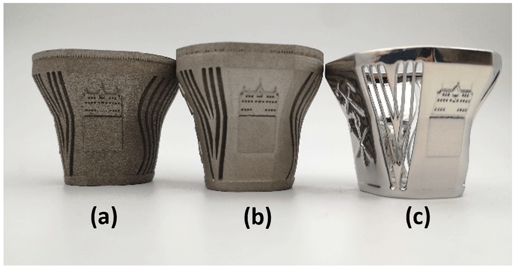
Figure 2.
AM stainless steel sample in various stages of post-processing; (a) as-built [part 0], (b) particle blasting-10 min. [part 1] and (c) PeP-70 min. [part 6].
Table 2. Surface roughness before and after polishing.
| Part No. | Polishing stages | Sa (µm) |
|---|
| 0 | As built | 19.8 |
| 1 | Particle blasting-10 min. | 6.8 |
| 2 | Particle blasting-20 min. | 6.4 |
| 3 | Particle blasting-30 min. | 5.7 |
| 4 | Particle blasting-10 min.
& PeP-3 min. | 5.8 |
| 5 | PeP-3 min. | 13.1 |
| 6 | PeP-70 min. | 2.6 |
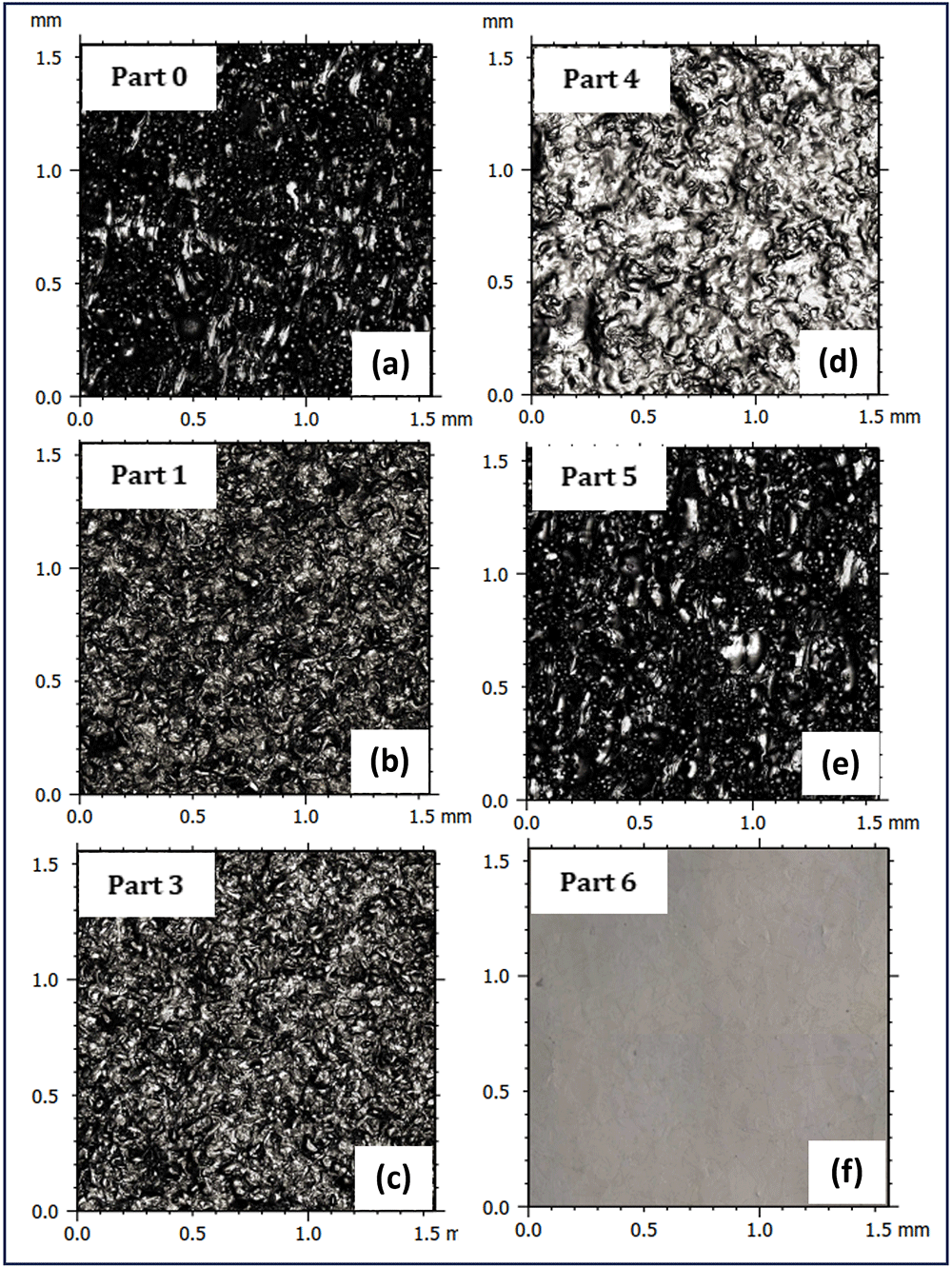
Figure 3.
Surface images of samples: (a) as built, (b) Particle blasting-10 min., (c) PeP-3 min., (d) particle blasting-10 min. & PeP-3 min., (e) Particle blasting-30 min. and (f) PeP-70 min.
The results clearly show that within the first 10 minutes of particle blasting on the printed sample, a 65% improvement in surface roughness (Sa = 19.8 µm to Sa = 6.8 µm) was achieved. Subsequent polishing with particle blasting improved the surface roughness to Sa = 6.4 µm and Sa = 5.7 µm after 20 and 30 minutes, respectively.
The result after PeP shows a decrease in surface roughness to Sa = 13.1 µm compared to the initial sample after 3 minutes of polishing and a decrease to Sa = 2.6 µm after 70 minutes of PeP. The combination of 3 minutes of PeP after 10 minutes of particle blasting resulted in a surface with a roughness value of Sa = 5.8 µm. This is interesting because the results obtained are very similar to those achieved after 30 minutes of particle blasting. This shows the importance of PeP as a final polishing method to significantly reduce the post processing time and improve the surface quality.
The results also show that the reduction in surface roughness with higher processing time is much smaller in the case of particle blasting compared to the initial 10 minutes. The combination of particle blasting with PeP as the final stage of polishing proves to be much more efficient than either method alone in terms of polishing time for parts with very high initial surface roughness as in this case.
Sample 6, which was polished with PeP for 70 minutes, exhibits the best surface properties compared to all other test samples. Although the polishing time is much longer, this experiment was performed only to show the gloss and aesthetics that can be achieved with this method. For samples with low initial surface roughness, a highly polished sample can be obtained with much shorter polishing times.
Conclusions
• Results show the effectiveness of using particle blasting and PeP in this sequence for post processing additively manufactured samples with very high surface roughness.
• The influence of particle blasting on the reduction of surface roughness is very large in the first few minutes, and the degree of roughness reduction decreases over time. The PeP process is much more efficient as a final polishing step to improve the productivity of the post processing line than when used alone on parts with high surface roughness.
• The study demonstrates the potential of the PeP process for polishing additively manufactured parts. It also explores the possible combination with particle blasting to optimize the post-processing workflow of AM and achieve the desired surface quality for use in real applications.
Ethics and consent
Ethical approval and consent were not required.
Data availability
Underlying data
EUDAT: Underlying data for ‘Plasma electrolytic polishing of additively manufactured metal parts: Optimizing the post processing workflow’, https://www.doi.org/10.23728/b2share.a49f1efd2eb440c3851de8b51eb9a45b1
This project contains the following underlying data:
● Figure 1: Schematic of PeP setup.
● Figure 2: AM stainless steel sample in various stages of post-processing; (a) as-built [part 0], (b) particle blasting-10 min. [part 1] and (c) PeP-70 min. [part 6].
● Figure 3: Surface images of samples (a) as built, (b) Particle blasting-10 min., (c) PeP-3 min., (d) particle blasting-10 min. & PeP-3 min., (e) Particle blasting-30 min. and (f) PeP-70 min.
● Table 1: Post processing stages of different samples.
● Table 2: Surface Roughness before and after polishing.
Data are available under the terms of the Creative Commons Zero “No rights reserved” data waiver (CC0 1.0 Public domain dedication).
Acknowledgements
The authors acknowledge the support received on printing the samples at Technion-Israel Institute of technology and Kristina Navickaite for the technical support received for roughness analysis at Technische Universität Bergakademie Freiberg-TUBAF.
Faculty Opinions recommendedReferences
- 1.
Edaklavan Koroth J, Valentinčič J, Jerman M, et al.:
Plasma electrolytic Polishing of additively manufactured metal parts: Optimizing the post processing workflow-Data. https://b2share.eudat.eu 2024. http://www.doi.org/10.23728/B2SHARE.A49F1EFD2EB440C3851DE8B51EB9A45B
- 2.
Nestler K, Böttger-Hiller F, Adamitzki W, et al.:
Plasma electrolytic Polishing - An Overview of Applied Technologies and Current Challenges to Extend the Polishable Material Range. In:
Procedia CIRP.
Elsevier B.V., 2016; 42: 503–507. Publisher Full Text
- 3.
Zeidler H, Böttger‐Hiller F:
Plasma‐Electrolytic Polishing as a Post‐Processing Technology for Additively Manufactured Parts.
Chemie Ingenieur Technik.
2022; 94(7): 1024–1029. Publisher Full Text
- 4.
Zeidler H, Aliyev R, Gindorf F:
Efficient Finishing of Laser Beam Melting Additive Manufactured Parts.
J Manuf Mater Process.
2021; 5(4): 106. Publisher Full Text