Introduction
The poor performance of column-base connections observed in the aftermath of several seismic events highlighted the significant need to advance current design and assessment strategies and to gain a more comprehensive and in-depth understanding of their behaviour (e.g., Clifton et al., 2011; Di Sarno et al., 2018; Gutiérrez-Urzúa et al., 2021; Mahin, 1998; Okazaki et al., 2013; among many others). Column-base connections typically need to transfer concurrently axial and shear forces, as well as bending moments from the superstructure to the foundation(s). Previous research has investigated the behaviour of different layouts of column-base connections, such as exposed base plate connections (e.g., Fasaee et al., 2018; Latour & Rizzano, 2013a; You & Lee, 2020) and embedded connections (e.g., Di Sarno et al., 2007; Grilli et al., 2017; Inamasu et al., 2021). Exposed base plate connections have conventionally been used in many European countries for low- to medium-rise steel frames. These connections consist of steel plates welded onto the column base and anchored to the foundation block through steel bolted bars. Stiffeners are also frequently used to enhance the rigidity of connections.
Current European codes offer limited guidance on the assessment and retrofit of column base connections. For example, the framework implemented in Eurocode 8-Part 3 (CEN, 2005b) for assessing existing steel buildings primarily accounts for beam-to-column connections and does not provide explicit guidance for column-bases. Besides, the component method adopted in the Eurocode 3-Part 1.8 (CEN, 2005a) predicts rotational stiffness and moment capacity of base-column connections. However, it does not allow the definition of the whole moment-rotation relationship, which requires a proper definition of the ultimate deformation capacity (Latour & Rizzano, 2013b; Latour et al., 2014).
Significant research effort has been dedicated recently to steel column-base connections. However, from one side, there has been a limited amount of experimental work; on the other side, most of the tests focused on uniaxial bending (e.g., Borzouie et al., 2015; Borzouie et al., 2016; Kanvinde et al., 2012; Latour et al., 2014; Lee et al., 2008a; Lee et al., 2008b; Zhou et al., 2004) and only a limited number of studies investigating the influence of biaxial bending (e.g., Cloete & Roth, 2021; Seco et al., 2021). Nevertheless, the performance of column-base plate connections has rarely been investigated through testing full-scale steel frames under bi-directional loading. There is also limited investigation into the impact of cumulative damage on such column-base connections resulting from repeated earthquakes.
To fill the knowledge gap, the H2020 EU-funded Earthquake Assessment of Base-Column Connections in Existing Steel Frames (HITBASE) project experimentally investigated the response of exposed column-base plate connections. Bi-directional Pseudo-Dynamic tests were carried out at the Structures Laboratory (STRULAB) of the University of Patras within the framework of Engineering Research Infrastructures for European Synergies (ERIES). The tests focused on a large-scale specimen extracted from a non-seismically designed steel frame. The specimen included two column-base plate connection typologies, i.e., stiffened and unstiffened, representing the base connections of external moment-resisting and internal gravity frames.
To facilitate data availability to the research community, the data which resulted from the testing campaign is stored to the public repository Zenodo and made openly available. This paper provides rich metadata to be employed in understanding and re-using the data provided by describing the experimental campaign and providing information on properties of the test specimens, construction, instrumentation, testing procedures, and the test matrix - some brief observations during the tests are included as well (more detailed description of specimen response will be covered in subsequent publications by the research team).
Description of the specimen
The test specimen is a full-scale, single-story, one-by-one bay steel frame representing a sub-structure of a non-seismically designed structure. The 5.75 m-long by 3.65 m-wide specimen features a height of 3 m to the mid-depth of a 0.25 m-thick reinforced concrete slab (Figure 1). The two columns on the South side of the structure (columns C1 and C2 in Figure 1a) have a HE160 section, while their counterparts on the North side (columns C3 and C4 in Figure 1a) have a HE140 section, thus resulting in a torsionally unbalanced structure. The perimeter beams are characterised by HE260 sections, while the four secondary transverse beams placed in the N-S direction at spacings of 1.10 m are made of IPE 220 sections.
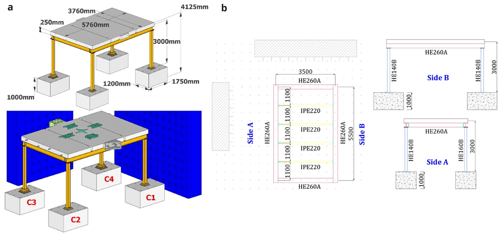
Figure 1.
Specimen geometry: (a) general view and column-naming; (b) plan-view and elevation (unit: mm).
All columns rest reinforced concrete footings with dimensions of 1 m × 1.75 m × 1.20 m (see Figure 1) made of C20/25 class concrete. The reinforced concrete slab, also made of C20/25 concrete, is connected to both perimeter and intermediate beams through 20 mm-in-diameter dowels spaced at 200 mm. All steel sections are built of S355 grade.
Different column-foundation connection details are used for columns on the North and South sides of the structure. Columns C1 and C2 (i.e., HE160 section) are welded via full-penetration welds to a 300-mm square 30 mm-thick bottom steel plate, which is anchored on the foundation via two Μ24 bars (Figure 2a). No stiffening plates are provided at the base of these two columns. On the other side, columns C3 and C4 (i.e., HE140 section) bear a stiffer connection to the foundation (Figure 2b) via a number of stiffening plates above the 370 × 400 mm base plate (30 mm-thick), where a 310 × 130 mm 25 mm-thick plate is welded underneath it and protrudes into a pocket in the foundation. Eight Μ24 bars of grade S355 steel are employed to provide anchorage to the RC foundation, which are post-tensioned to 150 kN. In all cases, a 50 mm-thick pad of high strength mortar is placed between each column base-plate and foundation, while for C3-C4 columns, the mortar is forced to also fill the pocket in the foundation for properly encasing the plates welded underneath the relevant base plates.
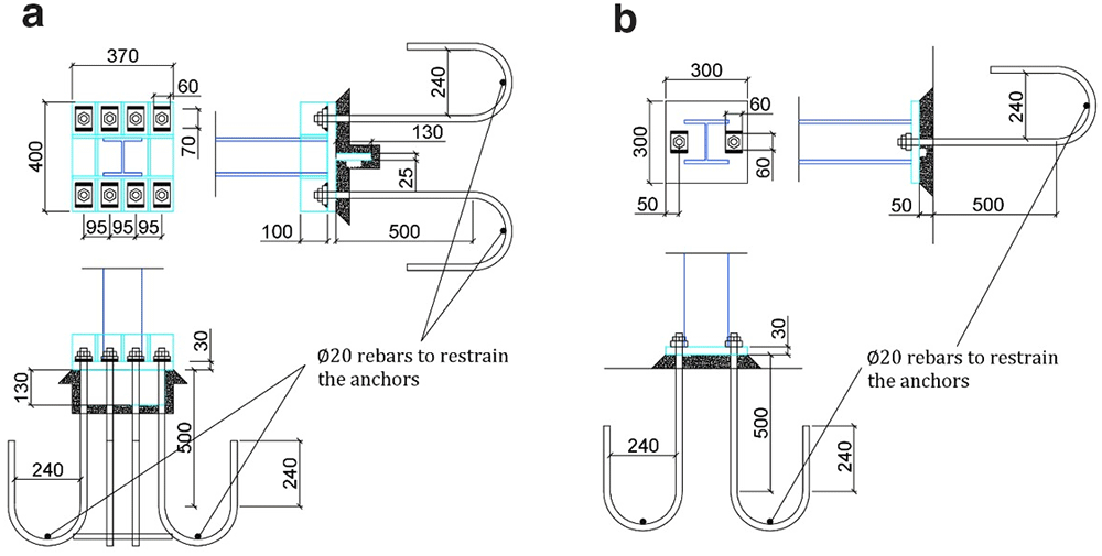
Figure 2.
Details of columns' base connection to foundation, for (a) columns C3–C4 and (b) columns C1 -C2 (unit: mm).
Moreover, the details of the beam-to-column, beam-to-beam and perimeter-to-secondary beam connections are depicted in Figure 3. For all these connections, 10.9 grade M16 bolts which are post-tensioned at 120 kN are employed.
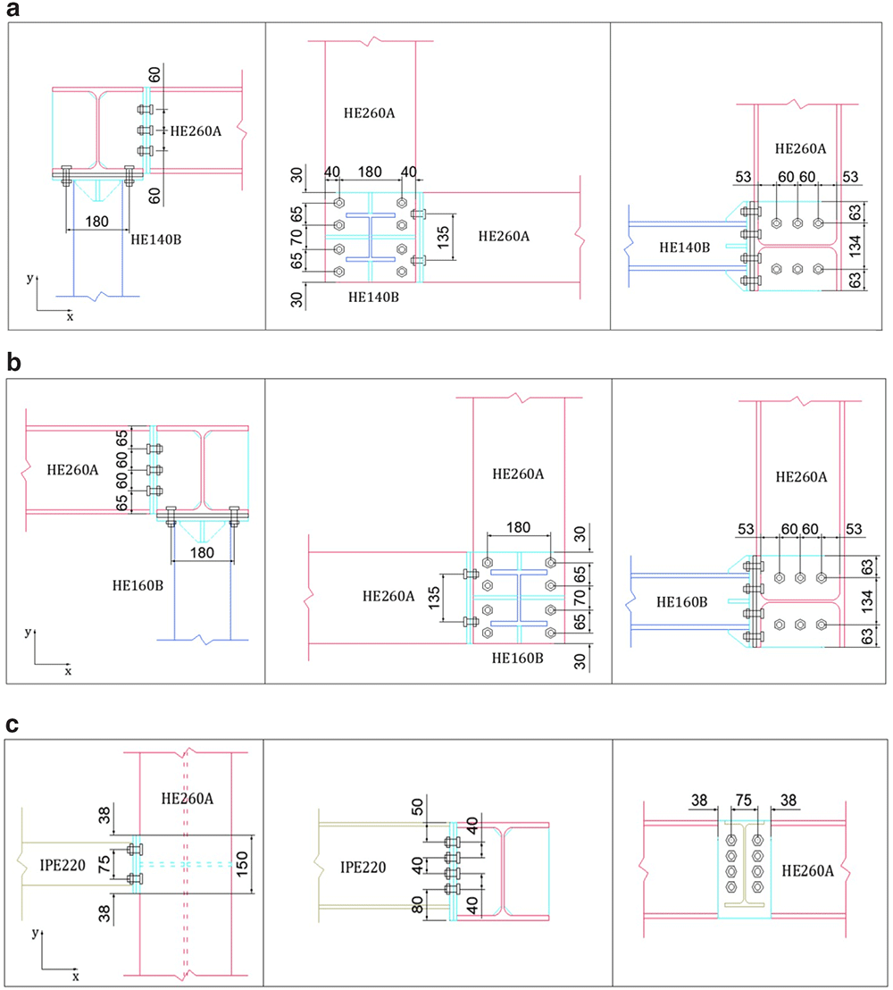
Figure 3.
Details of connections: (a) HE140-column-beam (North-side), (b) HE160-column-beam (South-side), and (c) secondary-to-perimeter beam (unit: mm).
The mechanical properties of the materials, as obtained from relevant material characterisation tests are summarised in Table 1. The mean compressive strength of the C20/25 concrete used for slab and foundation was determined over six samples, which are 32.3 and 34.2 MPa respectively. Moreover, the yield and ultimate strength of the S355 steel were also determined for each steel profile used by the specimen. The yield strength was measured to be between 370 and 431 MPa, while the ultimate strength was between 487 and 560 MPa. In addition, the mean compressive strength of the mortar was 47.1 MPa, measured on 50-mm cube samples.
Table 1. Mechanical properties of materials (units: MPa).
| Concrete (C20/25) | Steel (S355) | Mortar |
|---|
| Slab | Foundation | HE 260A | HEB 140 | HEB 160 | IPE220 |
|---|
| Mean strength | 32.3 | 34.2 | | | | | 47.1 |
| Yield strength | | | 431 | 370 | 431 | 391 | |
| Ultimate strength | | | 549 | 505 | 560 | 487 | |
Test setup and instrumentation
The test setup is shown in Figure 4. Additional masses (i.e., concrete blocks) of 15.76 tons were placed on the slab to simulate the mass of non-structural components and other loads. With the size of the slab exceeding crane capacity and the perimeter beams being permanently connected to the slab via dowels, dismantling the slab-plus-beams ensemble after testing would have been problematic. This issue was solved by pouring the slab in three different phases, not allowing for reinforcement to cross the interface sections and by finally post-tensioning the three pieces to guarantee monolithicity.
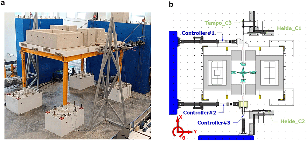
Figure 4.
(a) Photo of the setup and (b) control equipment and naming scheme.
The test aimed to investigate the response of the structure along both directions. Employing pseudo-dynamic test of an asymmetric 3D-frames, the testing method requires the use of sufficient number of actuators to provide the deformation pattern sought, i.e., translational displacements along the main axes, plus rotation about the vertical one. The loading scheme providing the required kinematics comprises a pair of actuators acting in tandem along the long direction of the frame and a third one acting in the transverse direction. The former controls frame displacement along the longitudinal dimension as well as its rotation, whilst the latter contributes to the control of frame displacement along the transverse direction.
The test process relies on the step-wise Pseudo-Dynamic method and involves a numerical and an experimental (physical) part: the former focuses on the step-by-step solution of the equation of motion of the system under a selected pair of seismic signals in two transverse directions. The resulting deformation vector (defined at the centre of mass of the system) comprises two transverse displacements and a rotation and, after being projected along the instantaneous directions of the longitudinal axis of each actuator, is applied to the structure - exact application of the displacement command signals is monitored via external, high resolution (2 μm) optical transducers (Figure 4b). The resulting reaction forces measured by the load cell on each actuator are transformed backwards to force components along the axes of the frame and sent to the numerical part to advance to the next load step.
Dense specimen instrumentation was employed on two diagonally opposite columns (C1 and C3 in Figure 1a). Response parameters (strain, deformation, inclination) at several points/sections were monitored - the type/position of the sensors is shown in Figure 5–Figure 10.
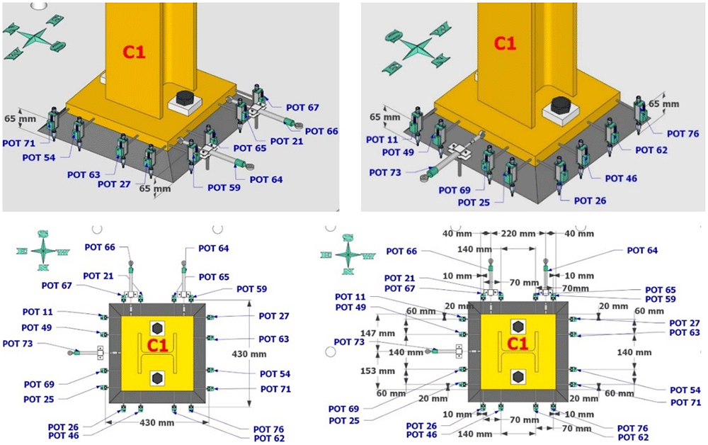
Figure 5. Potentiometers recording lateral and vertical deformations at the base of column C1.
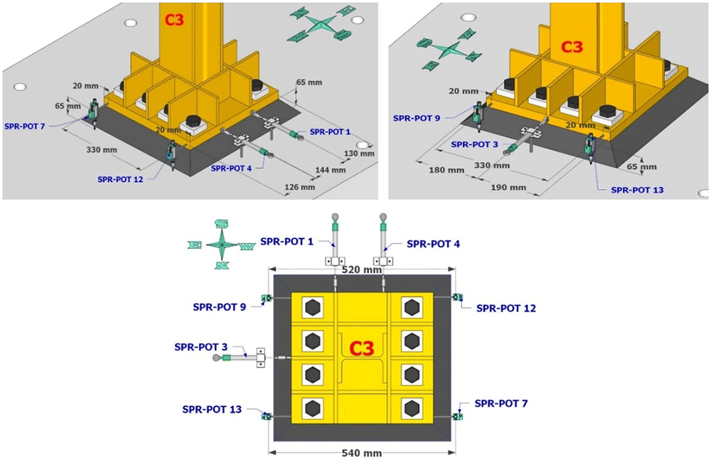
Figure 6. Potentiometers recording lateral and vertical deformations at the base of column C3.
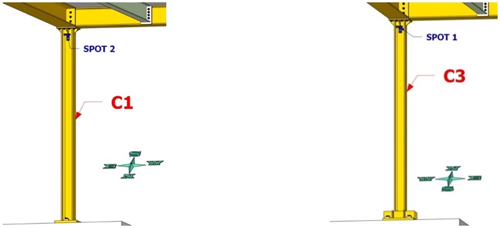
Figure 7. Position of string potentiometers measuring axial deformation along columns C1, C3.
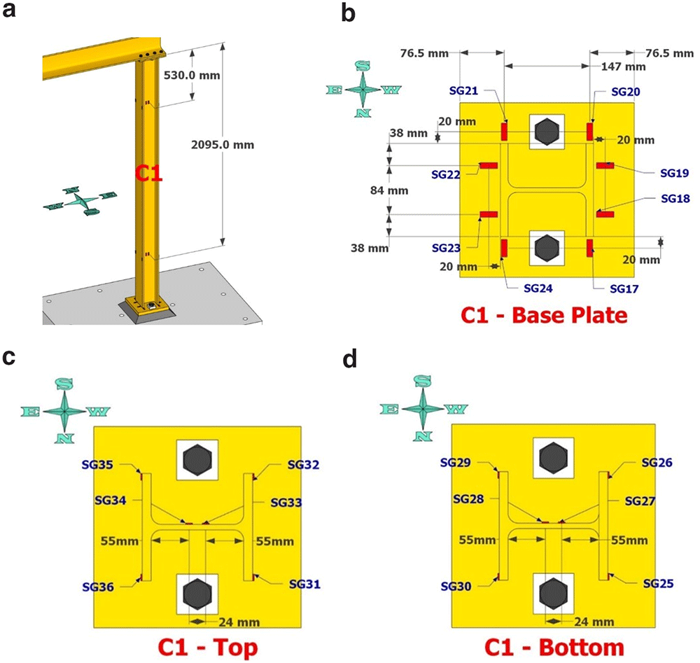
Figure 8.
Column C1 strain-gage instrumentation: (a) at 530- and 2095mm from column top; (b) gages on base plate; (c) gages as placed at section 530mm from top; (d) gages at section 2095mm from top.
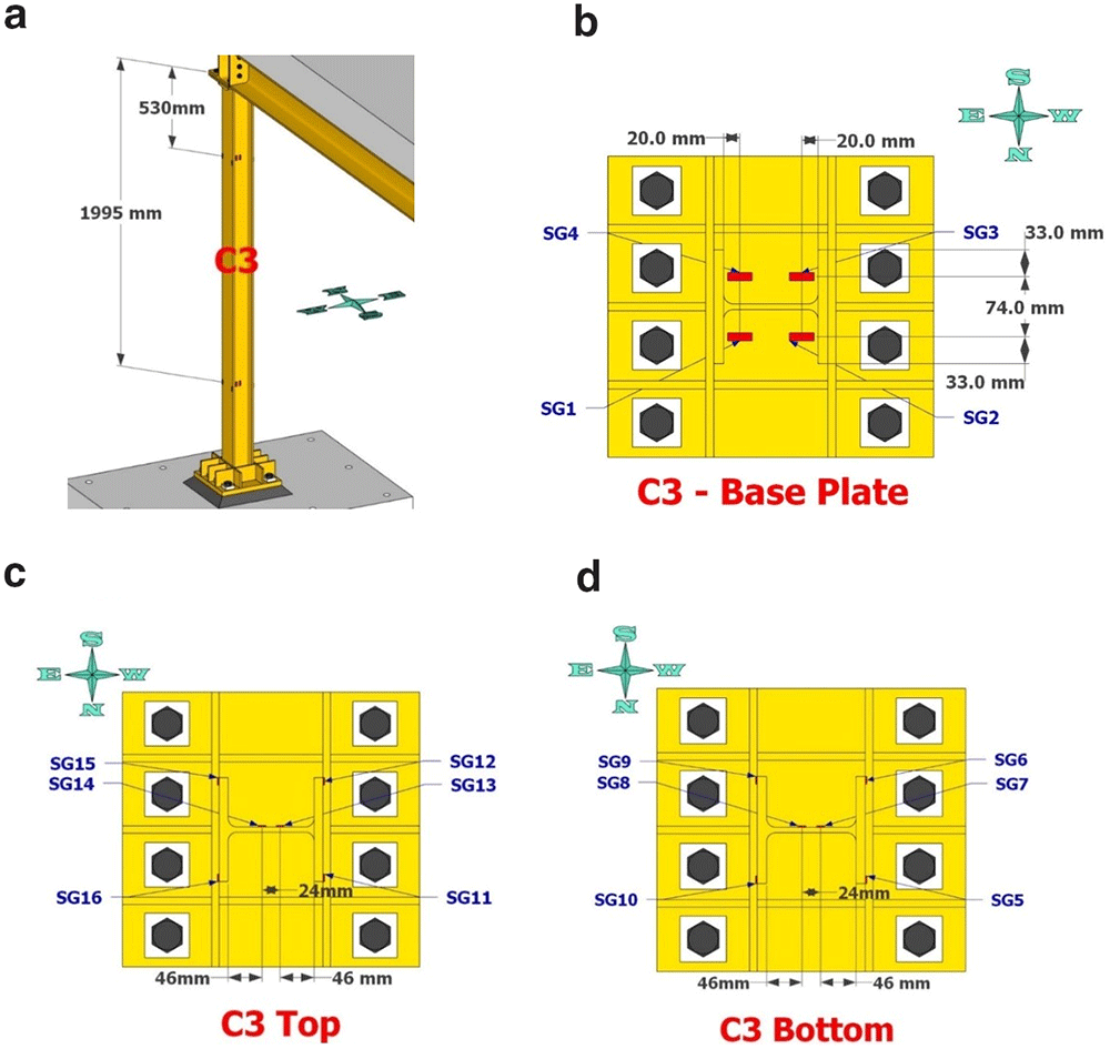
Figure 9.
Column C3 strain-gage instrumentation positioning: (a) along column height; (b) on base plate; (c) at 530mm from top; (d) at 1995mm from top.
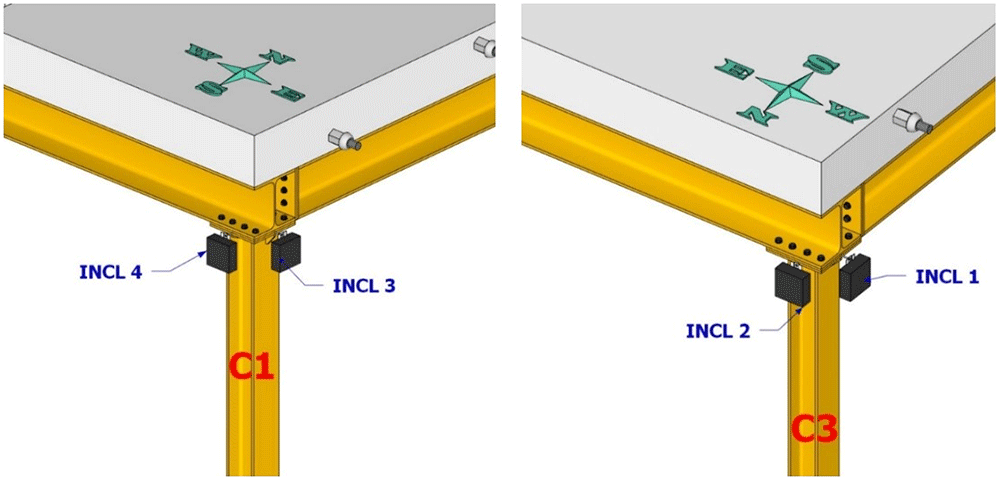
Figure 10. Position of inclinometers at top section of columns C1 and C3.
Excitation
As the scope of the tests includes the study of the effects of sequential seismic records occurring concurrently in orthogonal directions, a pair of sequentially applied natural earthquake signals were studied for being applied in the longitudinal and transverse direction of the structure, commencing and finishing concurrently (Figure 11). Two ground motion records referring to the 2016 Central Italy earthquakes were selected for this purpose - the records were extracted from the Engineering Strong-Motion Database (ESM) (Luzi et al., 2020). Preliminary analyses considering different combinations regarding the specimen axis along which each one of the pairs is applied and the direction (sign) of each record in the combination, led to the conclusion that the most detrimental combination would be with record in Figure 11a been applied along the longitudinal (E-W) specimen (Y) axis, while record in Figure 11b being applied along N-S specimen (X) axis. Next, scaled versions (20%-, 60%-, 100%-, 120%- and 150%-scale) of these two "basic" records were considered of being applied sequentially, with the ensemble of acceleration time histories finally applied concurently along X and Y directions of the structure being depicted in Figure 11c.
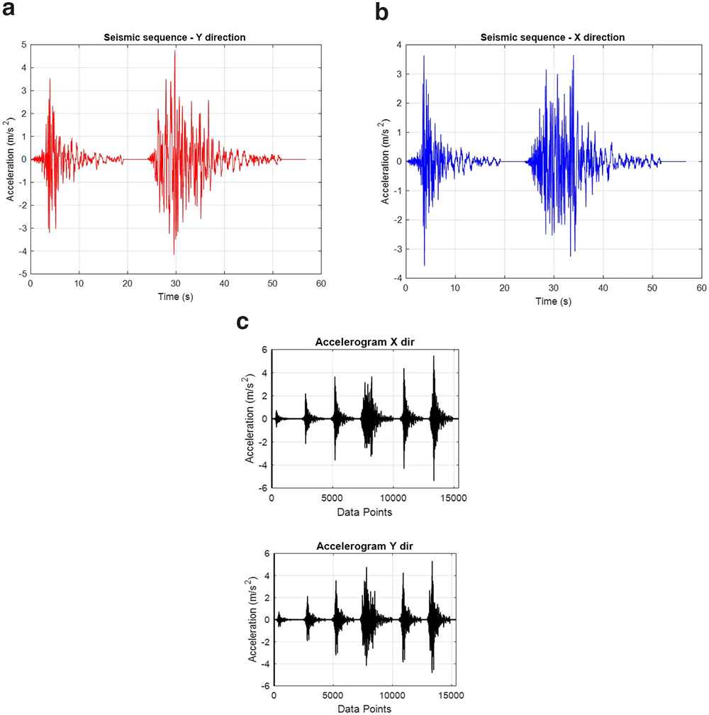
Figure 11.
Seismic records for the: (a) longitudinal, Y-direction, (b) transverse, X-direction and, (c) final sequence of records (X,Y) as applied.
Testing program
The test matrix developed for the experimental campaign is summarised in Table 2 and in the same way was the dataset organised.
Table 2. Test matrix for the 3D steel frame specimen in the laboratory.
| No. | Description | Note |
|---|
| 1 | Free vibration test: Y direction | 10-mm pull-back |
| 2 | Free vibration test: X direction | 10-mm pull-back |
| 2 | Quasi-static cyclic test: X direction | max. displacement: ± 27.5 mm |
| 4 | Quasi-static cyclic test: Y direction | max. displacement: ± 27.5 mm |
| 5 | Pseudo-dynamic test | two concurrent sequences of records applied |
The specimen was first subjected to free vibration tests along both of its main axes to identify its modal properties. Subsequently, the specimen was subjected to quasi-static cyclic tests also along both of its main axes, which reached a maximum floor displacement of 27.5 mm in both directions. Finally, a series of pseudo-dynamic tests were performed on the specimen using the pre-selected ground motion records, considering incremental scaling factors for the ground motion intensity from 0.2 to 1.5.
Free vibration test
The free vibration tests (layout demonstrated in Figure 12, "Tempo"-"Heide" denote optical displacement sensors and "Acc*_*" denote accelerometers) were performed along each of the main axis of the specimen, yielding the dynamic properties of the specimen per Table 3. The first global mode of the specimen was identified via free vibration in the X direction, which is a translational mode along the X direction with a period of 0.69 sec. The second and third global modes, associated with periods of 0.62 and 0.49 sec, are found to be rotational modes due to the asymmetry of the specimen in the Y direction caused by the different configurations of column base connections.
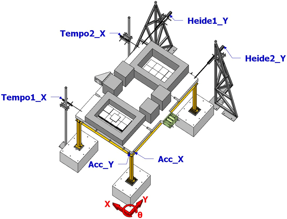
Figure 12. Free vibration testing layout.
Table 3. Periods of vibration of the specimen.
| Vibration direction | Mode 1 | Mode 2 | Mode 3 |
|---|
| Y (E-W) | - | 0.62 sec (rotational) | 0.49 sec (rotational) |
| X (N-S) | 0.69 sec (translational X) | - | - |
Photos and videos
The specimen response was monitored and recorded via cameras, both for what regards the overall vibration response of the specimen, as well for what concerns the response at the bases of the columns (which was also the target of the research).
Photographic documentation during the construction of the specimen and photos taken both during testing and following completion of the campaign, are shared with the dataset. Videos recorded during testing are also shared with the dataset.
Test observations
Excessive torsion of the specimen was observed during testing due to the different types of connections employed at the column bases (deformed shape of the structure shown in Figure 13). This resulted significant local damage at beam-to-column and column-base connections, such as fracture of welds and yielding of plates at the top of columns, plus cracking of the mortar beneath the column-base plates (see Figure 14 for examples of local damage).
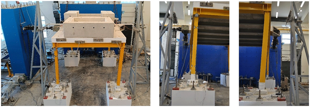
Figure 13. Deformed shape of the specimen.
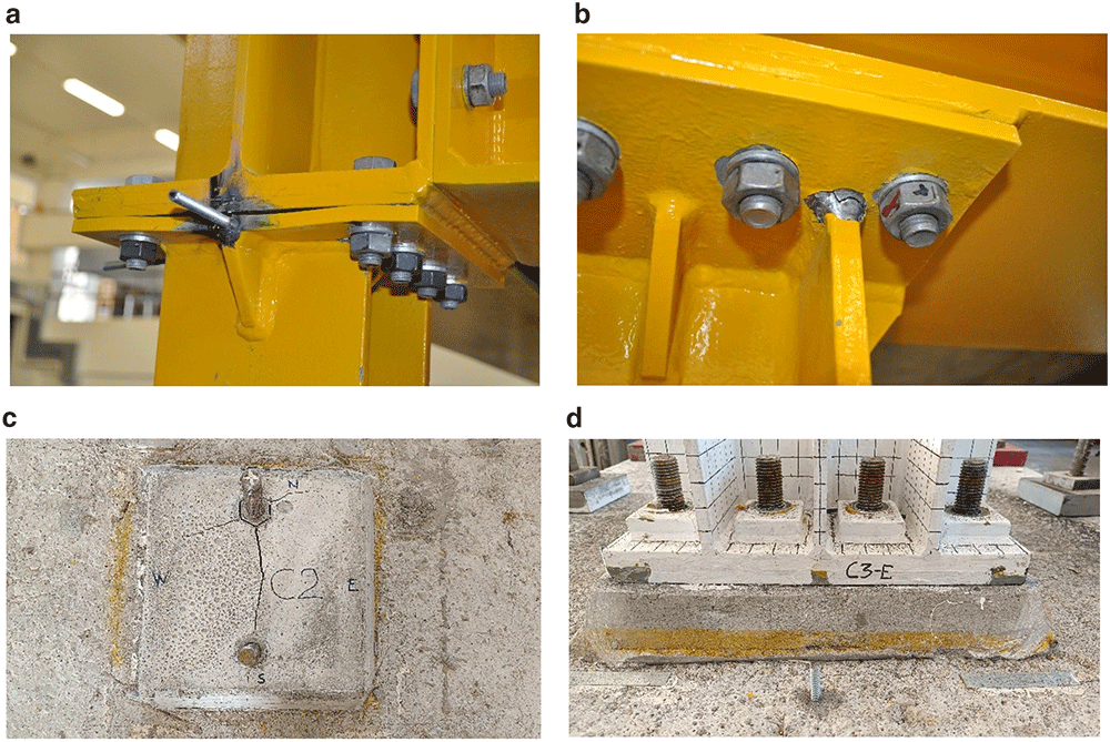
Figure 14.
Examples of damage observed during the pseudo-dynamic tests: (a) yielding of plates; (b) fracture of welds; (c) cracking of the mortar beneath the unstiffened column-base connection; (d) limited damage at the stiffened column-base connection.
Ethics and consent
Ethical approval and consent were not required.
Data availability
Underlying data
The complete dataset produced by this experimental campaign is available on the public repository Zenodo - https://doi.org/10.5281/zenodo.10866777 (Stathas et al., 2024). On the basis of the ERIES Transnational Access Agreement and the research team regarding data publication, the files will be made publicly available on September 30, 2024. Earlier access to the data may be provided to reviewers upon conrtacting ORE Editorial Team.
The project dataset is structured in four folders, comprising the metadata regarding general information, the specimen and the campaign (geometry, materials, test setup, excitation signals applied in each experiment, etc.). The actually measured data (values) are provided as Excel files in separate folders (one per test performed), clearly designating at the first lines of each file the physical parameter represented in each column and the relevant units. Photos and videos are also provideed, stored in different (evidently named) folders.
Data are available under the terms of the Creative Commons Attribution 4.0 International license (CC-BY 4.0)
Faculty Opinions recommendedReferences
- Borzouie J, MacRae GA, Chase JG, et al.:
Experimental studies on cyclic performance of column base weak axis aligned asymmetric friction connection.
J Constr Steel Res.
2015; 112: 252–262. Publisher Full Text
- Borzouie J, MacRae GA, Chase JG, et al.:
Experimental studies on cyclic performance of column base strong axis–aligned asymmetric friction connections.
J Struct Eng.
2016; 142(1): 04015078. Publisher Full Text
- CEN: EN 1993-1-8: 2005. Eurocode 3: design of steel structures. Part 1-8: design of joints, comité Européen de normalisation.
Brussels,
2005a. Reference Source
- CEN: EN 1998-1: 2005. Eurocode 8: design of structures for earthquake resistance - Part 1: general rules, seismic actions and rules for buildings, comité Européen de normalisation.
Brussels,
2005b. Reference Source
- Clifton C, Bruneau M, MacRae G, et al.:
Steel structures damage from the Christchurch earthquake series of 2010 and 2011.
B New York Soci Earthq Eng.
2011; 44(4): 297–318. Reference Source
- Cloete R, Roth CP:
Column base connections under compression and biaxial moments: experimental and numerical investigations.
J Constr Steel Res.
2021; 184(11): 106834. Publisher Full Text
- Di Sarno L, Paolacci F, Sextos AG:
Seismic performance assessment of existing steel buildings: a case study.
Key Eng Mat.
2018; 763: 1067–1076. Publisher Full Text
- Di Sarno L, Pecce MR, Fabbrocino G:
Inelastic response of composite steel and concrete base column connections.
J Constr Steel Res.
2007; 63(6): 819–832. Publisher Full Text
- Fasaee MAK, Banan MR, Ghazizadeh S:
Capacity of exposed column base connections subjected to uniaxial and biaxial bending moments.
J Constr Steel Res.
2018; 148: 361–370. Publisher Full Text
- Grilli D, Jones R, Kanvinde A:
Seismic performance of embedded column base connections subjected to axial and lateral loads.
J Struct Eng.
2017; 143(5): 04017010. Publisher Full Text
- Gutiérrez-Urzúa LF, Freddi F, Di Sarno L:
Comparative analysis of code-based approaches for seismic assessment of existing steel moment resisting frames.
J Constr Steel Res.
2021; 181: 106589. Publisher Full Text
- Inamasu H, Kanvinde AM, Lignos DG:
Seismic design of non-dissipative embedded column base connections.
J Constr Steel Res.
2021; 177: 106417. Publisher Full Text
- Kanvinde AM, Grilli DA, Zareian F:
Rotational stiffness of exposed column base connections: experiments and analytical models.
J Struct Eng.
2012; 138(5): 549–560. Publisher Full Text
- Latour M, Piluso V, Rizzano G:
Rotational behaviour of column base plate connections: experimental analysis and modelling.
Eng Struct.
2014; 68: 14–23. Publisher Full Text
- Latour M, Rizzano G:
Full strength design of column base connections accounting for random material variability.
Eng Struct.
2013a; 48: 458–471. Publisher Full Text
- Latour M, Rizzano G:
A theoretical model for predicting the rotational capacity of steel base joints.
J Constr Steel Res.
2013b; 91: 89–99. Publisher Full Text
- Lee DY, Goel SC, Stojadinovic B:
Exposed column-base plate connections bending about weak axis: I. numerical parametric study.
Int J Steel Struct.
2008a; 8(1): 11–27. Reference Source
- Lee DY, Goel SC, Stojadinovic B:
Exposed column-base plate connections bending about weak axis: II. experimental study.
Int J Steel Struct.
2008b; 8(1): 29–41.
- Luzi L, Lanzano G, Felicetta C, et al.:
Engineering Strong Motion Database (ESM) (Version 2.0). Istituto Nazionale di Geofisica e Vulcanologia (INGV). 2020. Publisher Full Text
- Mahin SA:
Lessons from damage to steel buildings during the Northridge earthquake.
Eng Struct.
1998; 20(4–6): 261–270. Publisher Full Text
- Okazaki T, Lignos DG, Midorikawa M, et al.:
Damage to steel buildings observed after the 2011 Tohoku-Oki earthquake.
Earthquake Spectra.
2013; 29(1_suppl): 219–243. Publisher Full Text
- Seco LDS, Couchaux M, Hjiaj M, et al.:
Column base-plates under biaxial bending moment.
Eng Struct.
2021; 231: 111386. Publisher Full Text
- Stathas N, Di Sarno L, Wu J, et al.:
Biaxial seismic response of base-column connections in sub-standard steel buildings: dataset. 2024. http://www.doi.org/10.5281/zenodo.10866777
- You YC, Lee D:
Effect of anchors on the seismic performance of exposed column-base plate weak-axis connections.
J Build Eng.
2020; 32: 101803. Publisher Full Text
- Zhou F, Suita K, Matsumiya T, et al.:
Tests on steel column bases with T-stub connections.
J Struct Constr Eng.
2004; 69(581): 117–125. Publisher Full Text